EasyManua.ls Logo

Sony TCS-60DV User Manual

Sony TCS-60DV
22 pages
To Next Page IconTo Next Page
Page #1 background imageLoading...
Page #1 background image
TCS-60DV
US Model
Canadian Model
AEP Model
E Model
SERVICE MANUAL
CASSETTE CORDER
MICROFILM
SPECIFICATIONS
Model Name Using Similar Mechanism TCM-50DV
Tape Transport Mechanism Type MT-50-30
Recording system 4-track 2 channel stereo
Tape speed 4.8 cm/s or 2.4 cm/s
Frequency range 250 – 8,000 Hz using nomal (TYPE1) cassette
(with REC TIME switch at “NORMAL”)
Speaker Approx. 3.6 cm (1
7
/16 in.) dia. ×2
Power output Speakers : 160 mW + 160 mW
(at 10 % harmonic distortion)
Headphones : 6 mW + 6 mW
(at 10 % harmonic distortion)
Input Microphone input jack (minijack) sensitivity
0.2 mV for 3 or lower impedance
microphone
Output 2 (headphones) jack (minijack) for
8 – 300 earphone
Variable range of the tape speed
From approx. +25 % to – 15 %
(with REC TIME switch at “NOMAL”)
Power requirements 3 V DC batteries AA (R6) ×2/
External DC 3 V power sources
Dimensions (w/h/d)(incl. projecting parts and controls)
Approx. 88.7 × 113.4 × 41.3 mm
(3
1
/2 × 4
1
/2 × 1
11
/16 inches), incl.
Mass Approx. 280 g (9.9 oz)
Design and specifications are subject to change without notice
Ver 1.0 1999. 03
Question and Answer IconNeed help?

Do you have a question about the Sony TCS-60DV and is the answer not in the manual?

Sony TCS-60DV Specifications

General IconGeneral
BrandSony
ModelTCS-60DV
CategoryCassette Player
LanguageEnglish

Summary

Key Specifications

Service Notes and Procedures

Main Board Removal Steps

Procedure for removing the Main board from the unit.

Fast Forward/Rewind Mode Activation

Steps to enter fast forward and rewind modes using test signals.

Playback Mode Activation

Steps to enter playback mode using test signals.

Record Mode Activation

Steps to enter record mode using test signals.

General Overview and Controls

Unit Controls and Indicators

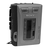
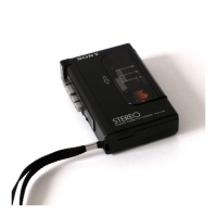
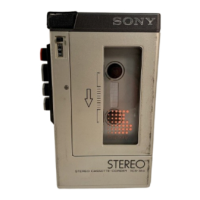
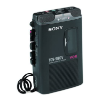
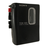
Identification and description of the unit's buttons, knobs, and indicators.

Disassembly Instructions

Cabinet, Lid, and Cassette Removal

Procedure for removing the rear cabinet, lid, and cassette assembly.

Main Board and Mechanism Deck Removal

Procedure for removing the main board and mechanism deck.

Drive Belt Replacement

Detailed guide on how to thread and replace the drive belts.

Magnetic Head Servicing

Procedure for removing and replacing the magnetic head.

DC Motor Removal

Main Board Reassembly Precautions

Precautions for correctly attaching the main board to the mechanism.

Adjustment Procedures

Mechanical Adjustment Steps

Procedures for mechanical adjustments, including torque and cleaning.

Electrical Adjustment Steps

Procedures for electrical adjustments, focusing on tape speed.

Circuit Diagrams and Schematics

System Block Diagram Overview

Block diagram illustrating the overall signal path and component connections.

Detailed Schematic Diagram

Detailed schematic diagram of the electronic circuits.

Main Board PCB Layout

LED Board PCB Layout

IC Block Diagrams

IC Pin Function Descriptions

Exploded Views

Main Section Exploded View 1

Exploded view of the main section, part 1, with component references.

Main Section Exploded View 2

Exploded view of the main section, part 2, with component references.

Mechanism Deck Exploded View 1

Exploded view of the mechanism deck, part 1.

Mechanism Deck Exploded View 2

Exploded view of the mechanism deck, part 2.

Electrical Parts Listing

Related product manuals