5-5
S MIC Chassis
5-2-3. Burst Gate Pulse Width Adjustment
(RV109)
Input signal: Color bars signal (LINE A/VIDEO IN)
Switches: UNDER SCAN 8 Pull (OFF)
16 : 9 8 Pull (4 : 3)
SYNC INT/EXT 8 INT
LINE/RGB 8 LINE
1. Connect an oscilloscope to pin 10 (COMP SYNC) of
CN104 and pin 1 (BGP GEN) of IC113.
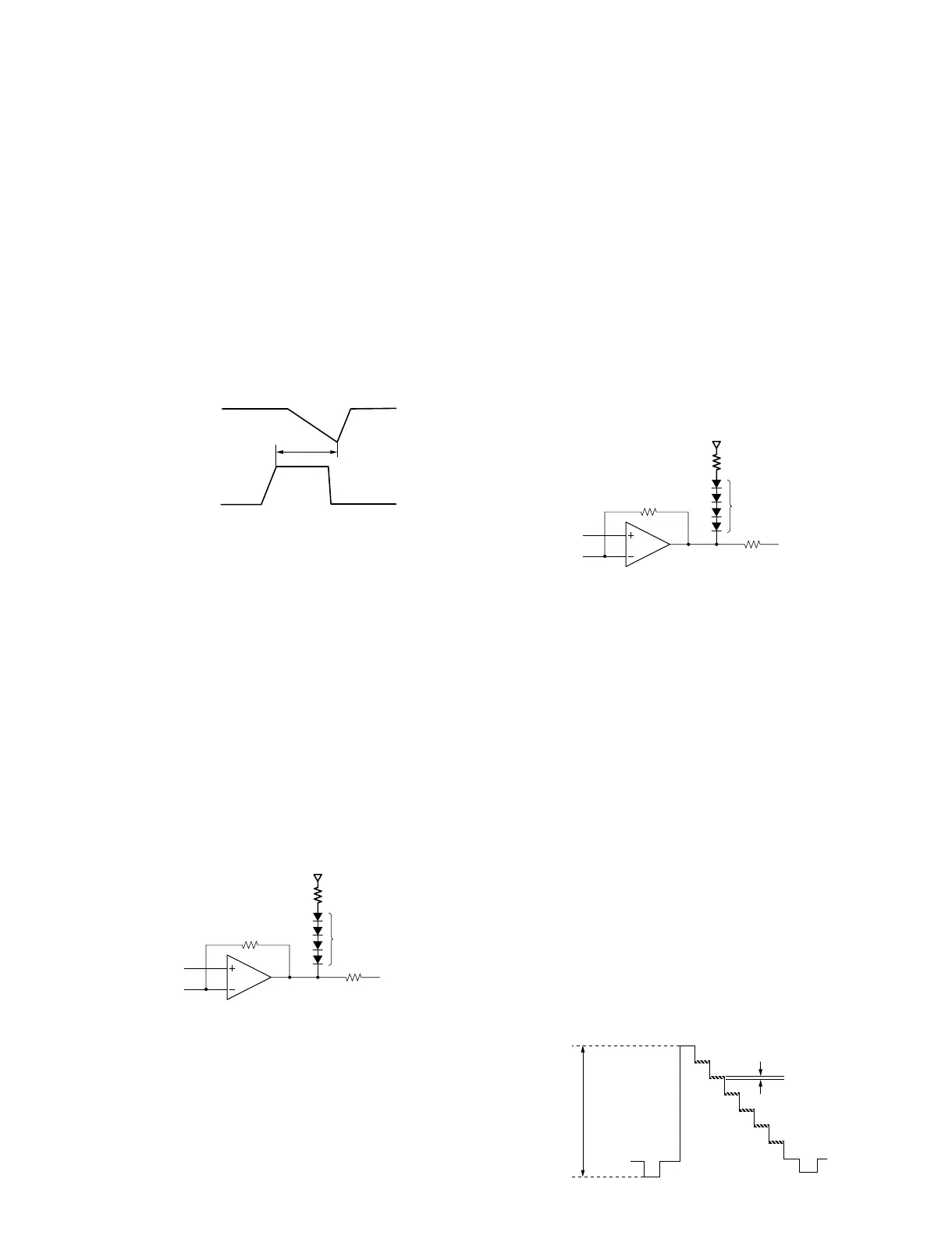
2. Adjust the pulse width (T) with RV109 (BGP WIDTH)
as shown below.
Specification: T = 7.8 ±0.2 usec
5-2-4. NTSC Subcarrier Frequency Adjustment
(RV1400)
Input signal: NTSC Color bars signal (LINE A/VIDEO IN)
Switches: UNDER SCAN 8 Pull (OFF)
16 : 9 8 Pull (4 : 3)
SYNC INT/EXT 8 INT
LINE/RGB 8 LINE
1. Apply +5 V to pin 26 of IC113 via 4.7 kZ resistor.
2. Connect pin 2 of IC109 to ground.
3. Connect the following circuit to pin 1 of IC113.
Part Required
Resistor 18 kZ ....................................................... 1 pc
Diode 1SS133 ........................................................ 4 pcs
4. Connect the frequency counter to pin 21 of IC113.
5. Adjust the frequency with RV1400 (3.58 F0).
Specification: F0 = 3,579,545 ±20 Hz
5-2-5. PAL Subcarrier Frequency Adjustment
(RV1401)
Input signal: PAL Color bars signal (LINE A/VIDEO IN)
Switches: UNDER SCAN 8 Pull (OFF)
16 : 9 8 Pull (4 : 3)
SYNC INT/EXT 8 INT
LINE/RGB 8 LINE
1. Apply +5 V to pin 26 of IC113 via 4.7 kZ resistor.
2. Connect pin 2 of IC109 to +12 V line.
3. Connect the following circuit to pin 1 of IC113.
Part Required
Resistor 18 kZ ....................................................... 1 pc
Diode 1SS133 ........................................................ 4 pcs
4. Connect the frequency counter to pin 21 of IC113.
5. Adjust the frequency with RV1401 (4.43 F0).
Specification: F0 = 4,433,619 ±20 Hz
5-2-6. NTSC Comb Filter Adjustment
(RV1, T1/CFM101)
Input signal: NTSC Color bars signal (LINE A/VIDEO IN)
Switches: UNDER SCAN 8 Pull (OFF)
16 : 9 8 Pull (4 : 3)
SYNC INT/EXT 8 INT
LINE/RGB 8 LINE
1. Connect an oscilloscope to minus (_) terminal of
capacitor C202, and confirm the Y and residual chroma
levels.
Specification:
Y level = 0.78 ±0.05 Vp-p
Residual chroma level = 32 mVp-p or less
2. If the residual chroma level is out of specification,
adjust RV1 and T1 alternately so that it is minimum.
+12 V
18 k
R211
R276
1
113
3
2
1S133 (x 4)
+12 V
18 k
R211
R276
1
113
3
2
1S133 (x 4)
0.78 ±0.05 Vp-p
Residual chroma:
32 mVp-p or less
C202 (_)
T = 7.8 ±0.2 uSec
IC113 PIN-1
CN104 PIN/0