7
Chapter 1 Overview
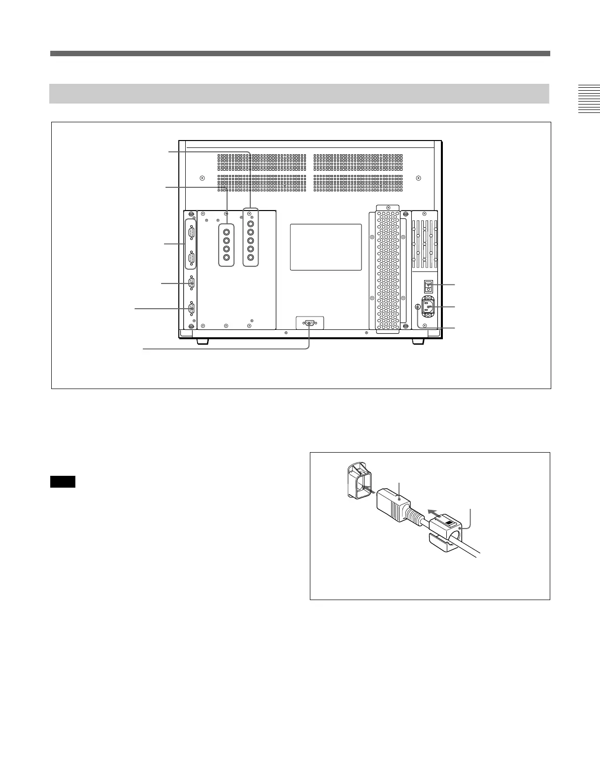
Rear Panel
1 MAIN POWER switch
2 AC IN socket
3 Fuse
8 ISR connector
4 RGB INPUT connectors
5 HD-SDI I/O connectors
6 REMOTE 1 connectors
7 REMOTE 2 connector
9 CONTROL UNIT
connector
Attach the AC Plug holder to the AC power cord, and
connect it to the AC IN socket so that the cord does not
come loose.
AC Plug holder (supplied)
AC power cord (supplied)
(continued)
1 MAIN POWER switch
When turned on, the monitor enters operation mode.
By setting in the SYSTEM CONFIGURATION menu,
the monitor can also be set to enter standby mode
when the MAIN POWER switch is turned on.
Note
When the monitor is turned on, “INITIALIZING” is
displayed. While it is displayed, the monitor cannot
accept commands from the BKM-10R/11R Monitor
Control Unit or the equipment connected to the serial
REMOTE 1 connector.
For information about the SYSTEM CONFIGURATION
menu, see “ [C4] Setting the Channel Selection Method and
Power-Up Conditions (SET UP 4) — SYSTEM
CONFIGURATION Menu” on page 39.
2 AC IN socket (3-pin)
Connects the monitor to an AC power source, via the
supplied AC power cord.
3 Fuse
Use a T4AH fuse.
 Loading...


