Do you have a question about the Sony TRINITRON KV-20FS12 and is the answer not in the manual?
| Screen Size | 20 inches |
|---|---|
| Display Type | CRT |
| Resolution | 480i |
| Aspect Ratio | 4:3 |
| Comb Filter | 3D Digital Comb Filter |
| Speakers | 2 |
| Inputs | Composite, S-Video |
Procedure for removing the rear cover of the TV chassis.
Steps to remove the main chassis assembly from the TV.
How to position the chassis for service.
Steps for safely removing the picture tube.
Adjusting the convergence of electron beams for picture clarity.
Aligning red, green, and blue electron beams for a sharp image.
Adjusting the picture focus for sharpness.
Adjusting screen grid voltage for optimal picture brightness.
Procedure to access and use the TV's service adjustment mode.
Calibrating color balance for accurate white reproduction.
Adjusting static convergence for vertical alignment.
Adjusting static convergence for horizontal alignment.
Performing dynamic convergence adjustments for optimal picture geometry.
Adjusting convergence at the screen corners using permalloy.
Verifying and adjusting HV hold-down circuit using R562.
Confirming and adjusting the B+ voltage supply line.
Explains the meaning of STANDBY/TIMER LED flash codes for diagnostics.
Method to stop the flashing STANDBY/TIMER LED.
Steps to clear diagnostic results to "0".
Procedure for measuring AC leakage current from metal parts to ground.
How to connect the TV to an antenna or CATV cable.
Connecting a TV to a VCR for playback and viewing.
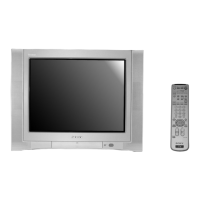
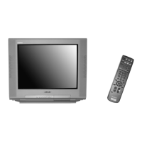
Explains the function of each button on the remote control.
Common TV problems and their suggested solutions for users.
Procedure to enter the TV's service adjustment mode.
What the screen displays upon entering service mode.
How to save settings in service mode.
How to verify that adjustments were saved correctly.
Identification of remote control buttons used for service adjustments.
Adjusting the horizontal size of the displayed image.
Adjusting the vertical size of the displayed image.
Adjusting the vertical position of the displayed image.
Adjusting the horizontal position of the displayed image.
Adjusting various picture geometry parameters.
Adjusting vertical angle, bowing, and pin distortion.
Checking the horizontal frequency in free run mode.
Checking the vertical frequency in free run mode.
Adjusting the RDRV signal for color and picture quality.
Adjusting the sub-brightness for optimal picture contrast.
Adjusting sub-hue and sub-color for accurate color representation.
Overall block diagram of the TV's electronic circuits.
Identifying the physical location of major circuit boards within the TV.
Schematics and wiring diagrams for various circuit boards.
Exploded view and parts list for the chassis of specific models.
Exploded view and parts list for the chassis of the KV-21FE12A model.
Exploded view and parts list for the chassis of specific models.
Exploded view and parts list for the chassis of specific models.
Corrects part numbers for IC1001 and IC1301 as per the service manual.