K
Kara WolfAug 20, 2025
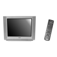
How to factory reset Sony TV?
- YymartinezAug 21, 2025
To reset your Sony TV to its original factory settings, turn on the TV. Then, while pressing and holding the RESET button on the remote control, also press the POWER button located on the TV's front panel. The TV will power off and then turn back on. Once it restarts, release the RESET button.