EasyManua.ls Logo

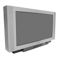
Sony Trinitron KV-35S40 User Manual

Sony Trinitron KV-35S40
85 pages
To Next Page IconTo Next Page
Page #1 background imageLoading...
Page #1 background image
1
KV-32S40/32S45/34SL40/34SL40C/34SL40T/34SL45/35S40/35S45/37SL45/
32V40/32V65/34VL65/34VL65C/35V65/37VL65/37VL65C
TRINITRON
®
COLOR TV
MODEL DEST. COMMANDER CHASSIS NO.
KV-32S40
US RM-Y165 SCC-S07A-A
KV-32S40
CND RM-Y165 SCC-S08A-A
KV-32S45
US RM-Y165 SCC-S07B-A
KV-32S45
CND RM-Y165 SCC-S08B-A
KV-34SL40T
TAIWAN RM-Y165 SCC-S16A-A
KV-34SL40C
E RM-Y165 SCC-S09A-A
KV-34SL40
E RM-Y165 SCC-S09B-A
KV-34SL45
E RM-Y167 SCC-S09C-A
KV-35S40
US RM-Y165 SCC-S07D-A
KV-35S40
CND RM-Y165 SCC-S08E-A
KV-35S45
US RM-Y167 SCC-S07E-A
KV-35S45
CND RM-Y167 SCC-S08F-A
KV-37SL45
E RM-Y167 SCC-S09F-A
KV-32V40
US RM-Y165 SCC-S07C-A
KV-32V40
CND RM-Y165 SCC-S08C-A
KV-32V65
CND RM-Y167 SCC-S08D-A
KV-34VL65
E RM-Y167 SCC-S09E-A
KV-34VL65C
E RM-Y167 SCC-S09D-A
KV-35V65
CND RM-Y167 SCC-S08G-A
KV-37VL65
E RM-Y167 SCC-S09G-A
KV-37VL65C
E RM-Y167 SCC-S09H-A
KV-35V65
SERVICE MANUAL
CHASSIS
AA-2D
RM-Y167

Questions and Answers:

Sony Trinitron KV-35S40 Specifications

General IconGeneral
BrandSony
ModelTrinitron KV-35S40
CategoryTV
LanguageEnglish

Summary

General Information

Connecting and Installing the TV

Guides through initial setup, connecting antenna/cable, and accessories.

Operating Video Equipment

Instructions for operating video equipment connected to the TV.

Operating a Cable Box or DBS Receiver

Guidance on connecting and operating cable boxes or DBS receivers.

Troubleshooting

Provides solutions to common problems encountered with the TV.

Disassembly Procedures

Rear Cover Removal

Step-by-step instructions for removing the rear cover of the TV.

Chassis Assembly Removal

Procedure for safely removing the main chassis assembly from the TV.

Service Position

Guidance on placing the TV in a suitable position for service.

Control Switch Removal

Instructions for removing the control switch assembly.

Picture Tube Removal (32"/34")

Procedure for removing the picture tube for 32-inch and 34-inch models.

Picture Tube Removal (35"/37")

Procedure for removing the picture tube for 35-inch and 37-inch models.

Set-Up Adjustments

Beam Landing Adjustment

Adjusting the beam landing for optimal picture geometry.

Convergence Adjustment

Procedure for adjusting color convergence for sharp picture display.

Focus Adjustment

Adjusting the focus control for a clear picture.

Screen (G2) and White Balance Adjustments

Adjusting screen (G2) and white balance for accurate color.

Safety Related Adjustments

R530, R531 Confirmation and Readjustments

Confirmation and readjustment method for components R530 and R531.

B+ Voltage Confirmation and Adjustment

Procedure for confirming and adjusting B+ voltage for safety.

Circuit Adjustments by Remote Commander

Setting the Service Adjustment Mode

Method for entering and navigating the TV's service adjustment mode.

Memory Write Confirmation Method

Procedure to confirm that adjustments are written into memory.

Remote Commander Adjust Buttons and Indicator

Details on buttons and indicators used on the remote for adjustments.

Diagrams and Schematics

S Series Block Diagram

Block diagram illustrating the signal flow for S series models.

V Series Block Diagrams

Block diagrams illustrating the signal flow for V series models.

Circuit Boards Location

Diagrams showing the physical location of circuit boards within the TV.

Printed Wiring Boards and Schematic Diagrams

Detailed PWB layouts and schematic diagrams for circuit analysis.

Exploded Views and Parts Identification

Chassis Exploded View (S Series)

Exploded view of the chassis for S series models, with part numbers.

Chassis Exploded View (35"/37" S Series)

Exploded view of the chassis for 35-inch and 37-inch S series models.

Chassis Exploded View (V Series)

Exploded view of the chassis for V series models, with part numbers.

Picture Tube Exploded View (KV-32V40/32V65/34VL65)

Exploded view of the picture tube assembly for specific V series models.

Picture Tube Exploded View (KV-35VL65C/35V65/37VL65/37VL65C)

Exploded view of the picture tube assembly for specific V series models.

Electrical Parts List

A Board Common Parts List (S Series)

List of common parts for the A board in S series models.

A Board Variant Parts List (S Series)

List of variant parts specific to models for the A board (S series).

A Board Common Parts List (V Series)

List of common parts for the A board in V series models.

A Board Variant Parts List (V Series)

List of variant parts specific to models for the A board (V series).

AV Board Complete Parts List

Complete list of parts for the AV board.

B Board Complete Parts List

Complete list of parts for the B board.

C Board Complete Parts List

Complete list of parts for the C board.

G Board Complete Parts List

Complete list of parts for the G board.

HS Board Complete Parts List

Complete list of parts for the HS board.

HV Board Complete Parts List

Complete list of parts for the HV board.

K Board Complete Parts List

Complete list of parts for the K board.

P Board Complete Parts List

Complete list of parts for the P board.

UV Board Complete Parts List

Complete list of parts for the UV board.

WA Board Complete Parts List

Complete list of parts for the WA board.

WB Board Complete Parts List

Complete list of parts for the WB board.

Accessories and Packaging Materials

List of accessories and packing materials included with the TV.

Related product manuals