4-1
SIIA Chassis
SECTION 4
SAFETY RELATED ADJUSTMENTS
Note: The “4-1. B
++
++
+ Voltage Check” and “4-2.
Protection Circuit (Hold-down circuit) Check”
should always be performed when replacing
the following components marked on the
schematic diagram.
A board
Marked products ( ) ....... C102, C331, C332, C333,
C334, C335, C341, C390,
C507, D102, D103, C1454,
IC001, IC301, IC552, L505,
Q102, R107, R108, R110,
R324, R325, R326, R327,
R328, R329, R330, T501
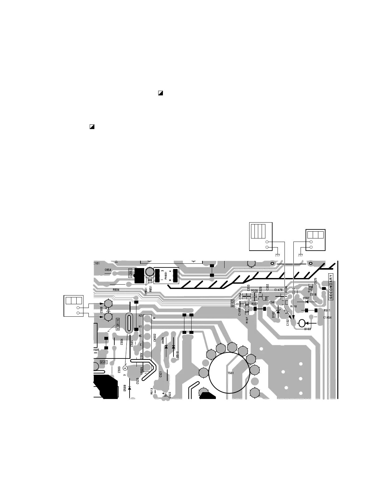
A BOARD (B SIDE)
4-1. B
++
++
+ VOLTAGE CHECK
Note: Be sure to use the NF power supply. If not, use
an ordinary power supply of its distortion
factor is 3 % or less.
Input voltage: 130 ±
3
Vac
0
Input signal: Black
Controls: BRIGHTNESS 8 Minimum
CONTRAST 8 Minimum
Specification: Confirm that the voltage at C500 on the
A board is 116.0 Vdc or less.
+
–
–
+
+
–
Digital multimeter
Digital multimeter
DC power supply
 Loading...