EasyManua.ls Logo

Sony WM-A52 - Page 6

Sony WM-A52
9 pages
Print Icon
To Next Page IconTo Next Page
To Previous Page IconTo Previous Page
Loading...
WM-A52/B52.
WM-A52/B52
1
2
3
|
4
5
6
7
8
9
on,
a
Ce
ee
|
,
14
15
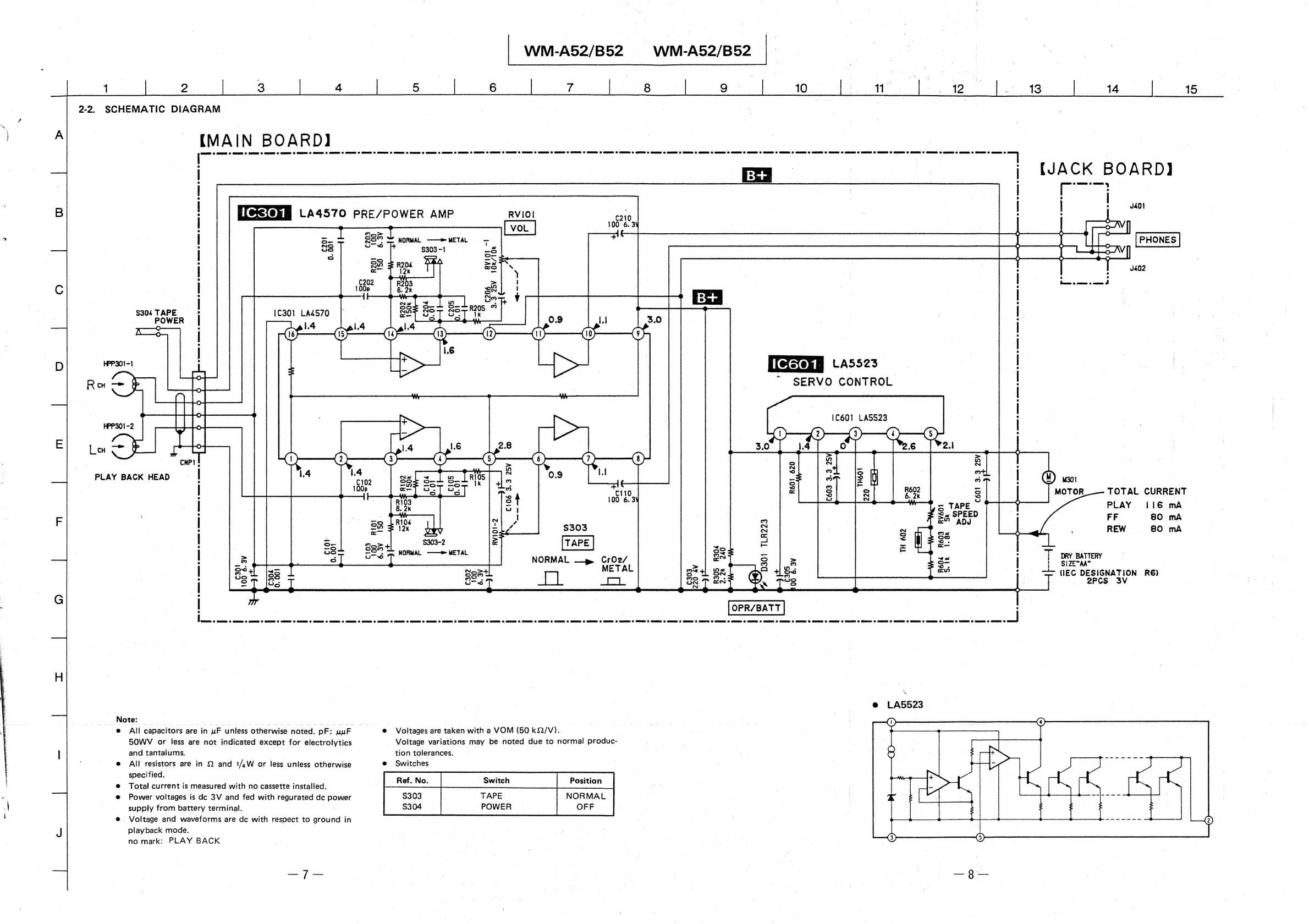
2-2.
SCHEMATIC
DIAGRAM
_
|
|
|
|
ta
|
[MAIN
BOARD]
oe
ferme
ep
rst
ae
er
es
arte
re ge
ee
ene
erage
nee
eRe
rem
ane
Foe ery
renee
ee
=
ate
eRe
eg
ene
acta
eere
ge
gC
oe
ge
age
a
eget
ca
7
|
:
;
{JACK
BOARD}
|
|
[
I
|
|
|
us0t
|
|
°
;
25°
NORMAL
——>METAL
+
[PHONES
|
|
=
.
03-1
:
:
Sram
F
BTS,
|
va
|
3
:
S304
TAPE
*
|
POWER)
|
;
A—c
i
H)
7
|
PPSO1-1
[fesekm
LAS523
|
HO
a
.
|
|
en
ae
|
SERVO
CONTROL
aap
|
Bae
1C601
LASS23
.
HPP301-2
ai
o D
S
o S
|
Lom
|
-
Cust
oT
es
Then
|
cRPI
!
=
(8)
ee
&
wn
-
PLAY
BACK
HEAD
|
on
(18
i
=
OW)
so
|
e
3
S
R602
3
MOTOR
TOTAL
CURRENT
|
S
PE
4
PLAY
116
mA
:
fate
FF
BO
mA
:
$303
he
REW
80
mA
|
:
|
NORMAL.
——™
METAL
So
=
zoe
,
|
NORMAL
Cr02/
aN
tx
j
DRY
BATTERY
|
METAL
S-
|
|
SIZETAAT
|
Bx
cus
:
<>
(IEG
DESIGNATION
R6)
7
ae
|
2PCS
3V
:
7
Note:
All
capacitors
are
in
uF
unless
otherwise
noted.
pF:
uur
50WV
or
less
are
not
indicated
except
for
electrolytics
and
tantalums.
All
resistors
are
in
2
and
1/,W
or
less
unless
otherwise
specified.
Total
current
is
measured
with
no
cassette
installed.
Power
voltages
is
dc
3V
and
fed
with
regurated
dc
power
supply
from
battery
terminal.
.
Voltage
and
waveforms
are
dc
with
respect
to
ground
in
playback
mode.
no
mark:
PLAY
BACK
|
Voltages
are
taken
with
a
VOM
(50
kQ/V).
Voltage
variations
may
be
noted
due
to
normal
produc-
tion
tolerances.
Switches
$303
$304
TAPE
|
POWER
NORMAL
OFF