Do you have a question about the Sony WM-FX415 and is the answer not in the manual?
Contains details on radio frequency, power, battery life, dimensions, mass, and accessories.
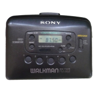
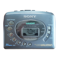
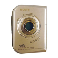
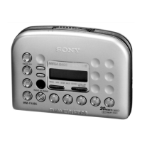
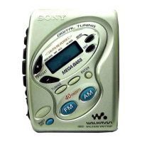
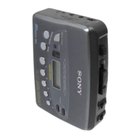
Describes the location and purpose of various buttons and controls on the device.
Details the procedure for removing the rear cabinet assembly, noting claw positions.
Explains how to remove the mechanism deck and main board.
Provides steps for removing the cassette lid, including releasing the hinge plate.
Outlines the procedure for removing the display board and its holder cover.
Offers guidance on installing components like the display board and torsion spring.
Details mechanical adjustments including head cleaning, demagnetization, and torque measurements.
Covers electrical adjustments for tape speed, FM, and AM tuning.
Explains FM tuning voltage and tracking adjustments using a signal generator and voltmeter.
Details AM tuning voltage, IF, and tracking adjustments.
Shows lead layouts for various semiconductors used in the device.
Lists pin functions for the IC401 Tuner Controller/LCD Drive.
Provides an exploded view of the cabinet and board assembly.
Displays an exploded view of the mechanism section.
| Type | Cassette Player |
|---|---|
| Brand | Sony |
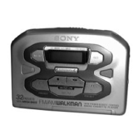
| Model | WM-FX415 |
| Tuner | FM/AM |
| Power Supply | 2 x AA batteries |
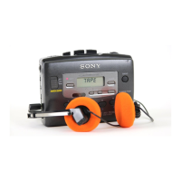
| Features | Mega Bass, Auto Reverse |
| Media type | Cassette |
| Mega Bass | Yes |
| Auto Reverse | Yes |
| Playback Speed | 4.76 cm/s |
| Wow and Flutter | 0.15% (WRMS) |