Do you have a question about the Sony WM-GX510 and is the answer not in the manual?
Details on operating controls and their functions.
Procedure for entering and operating the service mode.
Diagrams illustrating tape movement during PLAY, REW, and FF.
Steps for disassembling the bracket and cassette holder.
Procedure for removing the tuner board.
Steps for disassembling the main and sub boards.
Specifications and procedures for torque measurements.
Procedure for adjusting tape speed using a test tape.
Electrical adjustments for the cassette section.
Adjustments for AM and FM tuner sections.
Layout of the printed wiring board for tuner and main sections.
Schematic diagram for the tuner section.
Schematic diagram for the main section.
Printed wiring board layout for the main section.
Pin functions for key ICs used in the device.
Exploded view of the case and related parts.
Exploded view of the main board and its components.
Exploded view of the tape mechanism components.
List of electrical parts for the ATS Flexible and Main boards.
List of electrical parts for Sub, Tuner, and Tuner Flexible boards.
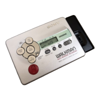
| Type | Cassette Player |
|---|---|
| Brand | Sony |
| Model | WM-GX510 |
| Playback Speed | 4.8 cm/s |
| Power Supply | 2 x AA batteries |
| Mega Bass | Yes |
| AVLS (Automatic Volume Limiter System) | Yes |
| Features | Auto reverse |
| Radio Tuner | AM/FM |
| Recording | Yes |
| Wow and Flutter | 0.15% |