後面 図
E
4
DC IN/HD/VD
(
DC
電源/同期信号入出力)
/VIDEO OUT
端子(
12
ピ
ンコネクター
)
カメラケーブル
CCXC-12P05N
などを接続して、
DC
+
12V
の電力の供給を
受けるとともに、カメラモジュールからの映像信号を送出します。また、同
期信号発生器を接続して外部同期信号(
HD/VD
信号)を入力すれば、カメラ
モジュールを外部同期で動作させることができます。この端子のピン
No.
と
入出力信号その他の関係は次の表のようになっています。
(端子のピン配置はイラストE
-
4
を参照してください。)
ピン番号
外部同期モード(HD/VD)
ピン番号
外部同期モード(HD/VD)
1
アース
7VD
入力
(
信号
)
2DC
+
12V 8 —
3
映像出力
(
アース
)9 —
4
映像出力
(
信号
)10 —
5HD
入力
(
アース
)11 —
6HD
入力
(
信号
)12VD
入力
(
アース
)
ピン番号 リスタートリセット 外部トリガーシャッター
1
アース アース
2DC
+
12V DC
+
12V
3
映像出力
(
アース
)
映像出力
(
アース
)
4
映像出力
(
信号
)
映像出力
(
信号
)
5HD
入力
(
アース
)HD
入力
(
アース
)
6HD
入力
(
信号
)HD
入力
(
信号
)
7
リセット
(
信号
)VD
入力
(
信号
)
8— —
9— —
10 — WEN
出力
(
信号
)
11 —
トリガーパルス入力
(
信号
)
12
リセット
(
アース
)VD
入力
(
アース
)
ピン番号 カメラ同期信号出力 ピン番号 カメラ同期信号出力
1 アース 7
VD
出力
(
信号
)
2
DC
+
12V
8 —
3 映像出力
(
アース
)
9 —
4 映像出力
(
信号
)
10 —
5
HD
出力
(
アース
)
11 —
6
HD
出力
(
信号
)
12
VD
出力
(
アース
)
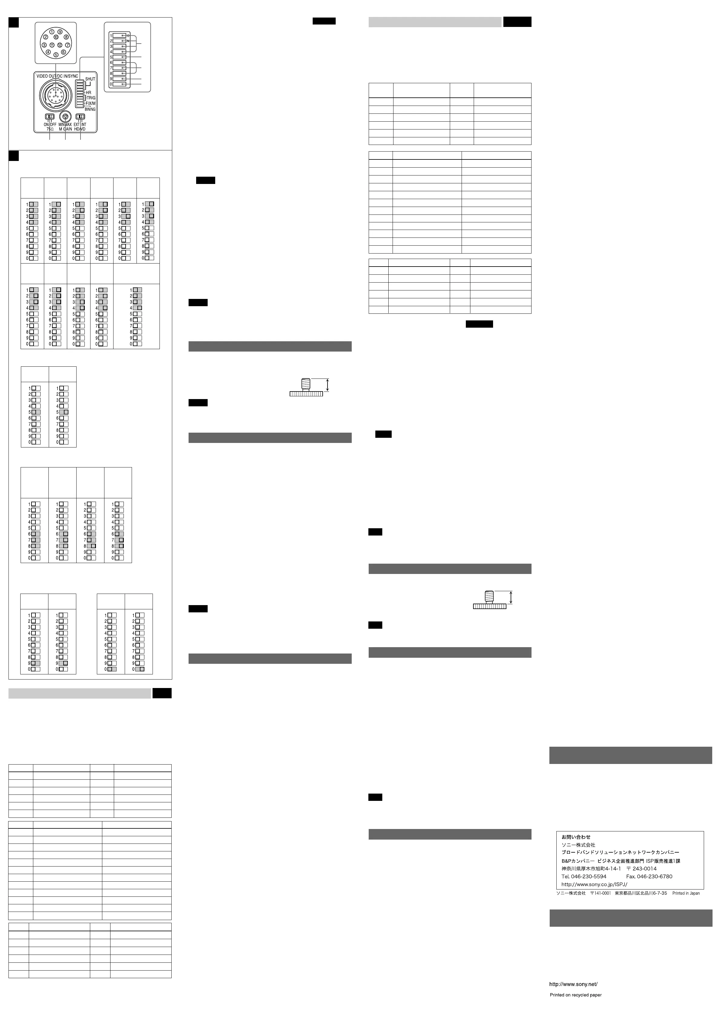
Rear Fig. E
4 DC IN/HD/VD (DC power input/sync signal I/O)/VIDEO OUT
connector (12-pin)
You can connect a CCXC-12P05N camera cable to input the +12V DC
power supply and to output the video signal from the camera module. When
a sync signal generator is connected to this connector, the camera module
is synchronized with the external sync signals. The pin configuration of this
connector is as follows.
(For details on the pin arrangement, see Figure E-4.)
Pin No.
External Sync mode
Pin No.
External Sync mode
(HD/VD) (HD/VD)
1 Ground 7 VD input (Signal)
2 +12V DC 8 —
3 Video output (Ground) 9 —
4 Video output (Signal) 10 —
5 HD input (Ground) 11 —
6 HD input (Signal) 12 VD input (Ground)
Pin No. Restart reset External trigger shutter
1 Ground Ground
2 +12V DC +12V DC
3 Video output (Ground) Video output (Ground)
4 Video output (Signal) Video output (Signal)
5 HD input (Ground) HD input (Ground)
6 HD input (Signal) HD input (Signal)
7 Reset (Signal) VD input (Signal)
8 ——
9 ——
10 — WEN output (Signal)
11 — Trigger pulse input (Signal)
12 Reset (Ground) VD input (Ground)
Pin No. Camera sync output Pin No. Camera sync output
1 Ground 7 VD output (Signal)
2 +12V DC 8 —
3 Video output (Ground) 9 —
4 Video output (Signal) 10 —
5 HD output (Ground) 11 —
6 HD output (Signal) 12 VD output (Ground)
5 Shutter speed/Mode setting DIP switch See Fig. F
1 Shutter speed (bits 1–4)
Set an appropriate shutter speed. See Figure F-a for the settings.
(Factory setting: OFF)
2 High rate scan mode (bit 5)
See Figure F-b for the settings. (Factory setting: OFF)
* To use the camera with the high rate scan mode set to ON, you
must set the pulse duration. For details, refer to the User’s Guide.
3 Restart reset/External trigger shutter mode switch (bits 6–8)
See Figure F-c for the settings. (Factory setting: Normal)
4 GAIN switch (bit 9)
This switch selects FIX (invariable) or MANUAL (manual adjustment).
See Figure F-d for the setting. (Factory setting: MANUAL)
5 Binning mode switch (bit 0)
See Figure
F
-e for the setting. (Factory setting: OFF)
* If you set the binning mode to ON, the amplitude or periodicity of
the video output signal will be changed. For details, refer to the
User’s Guide.
Notes
• Do not use any other settings for Restart reset/External trigger shutter
mode except those shown in Figure F-c. Using other settings may
cause the camera to malfunction.
• If you set the External trigger shutter mode, set 0 in bits 1–4.
6 HD/VD signal input/output switch
Set the switch to INT to output the HD/VD signals from the camera module.
Set the switch to EXT to input the HD/VD signals from an external unit.
(Factory setting: EXT)
7 Manual GAIN (M GAIN) control knob
If you have set DIP switch 5-4 to MANUAL (manual adjustment), you can
control the gain manually by adjusting this knob.
8 75Ω termination switch
Turn off if you do not terminate. (Factory setting: ON)
Note
When flipping/adjusting the switches/knobs (5 to 8), use drivers that
appropriate for the parts of the system which you intend to adjust.
Otherwise, malfunctions may occur.
Using a tripod
To use the tripod, install the tripod adaptor VCT-333I (not supplied) on the
camera module.
Use a tripod screw with a protrusion (4) extending
from the installation surface, as follows:
ISO standard: Length 4.5 mm ±0.2 mm
ASA standard: Length 0.197 inches
Note
If you install a tripod adapter (not supplied), use the screws provided.
Typical CCD Phenomena
The following effects on the monitor screen are characteristic of CCD
cameras. They do not indicate any fault with the camera module.
Smear
This occurs when shooting a very bright object such as electric lighting, the
sun, or a strong reflection.
This phenomenon is caused by an electric charge induced by infrared
radiation deep in the photosensor. It appears as a vertical smear, since the
CCD imaging element uses an interline transfer system.
Vertical aliasing
When you shoot vertical stripes or lines, they may appear jagged.
Blemishes
A CCD image sensor consists of an array of individual sensor elements
(pixels). A malfunctioning sensor element will cause a single pixel blemish
in the picture. (This is generally not a problem.)
White speckles
When you shoot a dark object at a high temperature, small white dots may
appear all over the image.
Note
If strong light enters a wide area of the screen, the screen may become
dark. This is not a malfunction. If this occurs, avoid strong light or adjust the
lens iris to reduce the light amount.
Specifications
Imaging system
Pickup device Progressive scan 1/3 type CCD
Effective picture elements (horizontal/vertical)
659 × 494
Optical blank 33 elements on each horizontal line
CCD vertical drive frequency
31.47 kHz ± 1%
CCD horizontal drive frequency
24.55 MHz
Cell size (horizontal/vertical)
7.4 × 7.4 µm
Chip size (horizontal/vertical)
5.84 × 4.94 mm
Optical system and others
Lens mount C-mount
Flange focal length 17.526 mm
Synchronization Internal/external
(automatically switched according to input signal)
External sync signal I/O
HD/VD (HD/VD level: 2-5 Vp-p)
External sync allowable frequency
±1% (of horizontal sync frequency)
H Jitter Less than 20 nsec
Video output 1.0 Vp-p, sync negative, 75 ohms unbalanced
Output signal frequency
59.94 Hz (normal mode)
Effective lines 648 × 494 (horizontal/vertical)
Horizontal resolution 500 TV lines
Sensitivity 400 lx, F5.6 (with the FIX gain)
Minimum illumination 1 lx (with the manual gain control at maximum,
F1.4)
Video S/N ratio 58 dB
Gain Fixed gain/Manual gain control
γ 1 (fixed)
White clip 820 mV ± 70 mV
Read mode normal/binning
Shutter External trigger shutter
Shutter speed External trigger shutter: 1/4 to 1/100000 sec.
Power +12 V DC (Range: +10.5 to 15 V)
Power consumption 1.8 W
Operating temperature
–5 to +45 °C (23 to 113 °F)
Storage temperature –30 to +60 °C (–22 to 140 °F)
Operating relative humidity
20 to 80 % (no condensation)
Storage relative humidity
20 to 95 % (no condensation)
Vibration resistance 10 G (20 Hz – 200 Hz)
Shock resistance 70 G
External dimension (w/h/d)
29 × 29 × 30 mm
(1 3/16 × 1 3/16 × 1 3/16 inches)
Mass 50 g (2 oz.)
Accessories Lens mount cap (1)
Operating Instructions (1)
Design and specifications are subject to change without notice.
4
About the User’s Guide
The Operating Instructions describe the functions and use of this
product.
For more details, see the User’s Guide. Please ask your sales
representative about the User’s Guide.
5 シャッタースピード/各種モード設定用
DIP
スイッチ
図
F
参照
1 シャッタースピード設定(
bit 1
〜
4
)
撮影条件に応じたシャッタースピードに設定します。それぞれの設定
位置はイラストF
-a
を参照してください。工場出荷時のスイッチ設定
はシャッター
OFF
です。
2 ハイレートスキャンモード切り換え(
bit 5
)
切り換え位置はイラストF
-b
を参照してください。工場出荷時のス
イッチ設定はハイレートスキャン
OFF
です。
*
ハイレートスキャンモードを
ON
にしてお使いになる場合には、別途
パルス幅の設定が必要となります。詳細はユーザーズガイドをご覧く
ださい。
3
リスタートリセット/外部トリガーシャッターモード切り換え(
bit 6
〜
8
)
各モードの設定位置はイラストF
-c
を参照してください。工場出荷時
のスイッチ設定はノーマルです。
4
Gain
(ゲイン)切り換えスイッチ(
bit 9
)
このスイッチの切り換えにより、
FIX
(固定)、
MANUAL
(手動調
整)の各モードが選択できます。設定位置はイラストF
-d
を参照して
ください。工場出荷時のスイッチ設定は
MANUAL
です。
5 ビニングモード切り換え(
bit 0
)
切り換え位置はイラストF
-e
を参照してください。工場出荷時のス
イッチ設定はビニング
OFF
です。
*
ビニングモードを
ON
にしてお使いになる場合には、映像信号出力の
振幅や周期が変化します。詳細はユーザーズガイドをご覧ください。
ご注意
• リスタートリセット/外部トリガーシャッターモードのときは、F
-c
に
示した設定以外の組み合せでは使用しないでください。誤動作のおそれ
があります。
• 外部トリガーシャッターモードに設定したときは
bit 1
〜
4
をすべて
0
の
位置にしてください。
6
HD/VD
信号入出力切り換えスイッチ
カメラモジュールから
HD/VD
信号を出力するときは
INT
側に、外部から
HD/VD
信号を入力するときは
EXT
側に設定します。工場出荷時は
EXT
側に
設定されています。
7 手動ゲイン(
M GAIN
)調整つまみ
DIP
スイッチ5
–
4で
MANUAL
(手動調整)に設定した場合、このつまみ
でゲインを調整できます。
8
75
Ω終端スイッチ
終端しないときは
OFF
にします。工場出荷時のスイッチ位置は
ON
です。
ご注意
5〜8のスイッチやつまみを操作する場合には、各操作部に適合したドライ
バーをお使いください。不適切な工具による無理な操作は故障の原因となり
ます。
三脚の取り付け
三脚アダプター
VCT-333I
(別売り)をカメラモジュールに取り付けてから
三脚に取り付けます。
三脚の取付部のネジは取付面からの飛び出し量(4)が下記のものを使用して
ください。
ISO
規格 4:
4.5mm
±
0.2mm
ASA
規格 4:
0.197
インチ
ご注意
三脚アダプター(別売り)を取り付けるときは、三脚アダプターに付属のネ
ジを使用してください。
CCD
特有の現象
CCD
カメラの場合、次のような現象が起きることがありますが、故障ではあ
りません。
スミア
高輝度の被写体を写したときに、明るい帯状の縦線(垂直スミア)がモニ
ター画面に見える現象です。
この現象は、
CCD
がインターライン転送方式を採用しているため、フォトセ
ンサーの深いところに入った赤外線などにより誘起された電荷が、レジス
ターに転送されるために起こるものです。
折り返しひずみ
縞模様、線などを写したとき、ぎざぎざのちらつきが見えることがありま
す。
傷
CCD
はフォトセンサー(素子)が縦横に並んでできており、フォトセンサー
のいずれかに欠陥があると、その部分だけ画像が写らず、モニター画面に傷
となって見えます(実用上支障がない程度)。
微小白点
高温時に暗い被写体を写している場合、画面全体に多数の白点が現れること
があります。
ご注意
強い光が画面の広い範囲に入射した場合、画面が暗くなることがありますが
故障ではありません。
この場合は強い光を避けるか、または入射光量をレンズで調整してくださ
い。
主な仕様
画像系
撮像素子 プログレッシブスキャン
1/3
型
CCD
有効画素数
659
×
494
(水平/垂直)
光学黒期間 各水平走査線のうち
33
画素
CCD
垂直駆動周波数
31.47 kHz
±
1
%
CCD
水平駆動周波数
24.55 MHz
セルサイズ
7.4
×
7.4
μ
m
(水平/垂直)
チップサイズ
5.84
×
4.94 mm
(水平/垂直)
光学系、その他
レンズマウント
C
マウント
フランジバック
17.526 mm
同期方式 内部/外部(入力信号に応じて自動切り換え)
外部同期入出力
HD/VD (HD/VD
レベル:
2
〜
5Vp-p)
外部同期許容周波数偏差
±
1
%(水平同期周波数に対して)
H
ジッター
20 nsec
以下
映像出力
1.0 Vp-p
、同期負、
75
Ω不平衡
出力信号周波数
59.94 Hz
(ノーマルモード時)
有効ライン数
648
×
494
(水平
/
垂直)
水平解像度
500 TV
本
感度
400 lx
、
F5.6
(
FIX GAIN
時)
最低被写体照度
1 lx
(
手動ゲイン調整最大時、
F1.4)
映像
S
/
N
比
58 dB
ゲイン 固定ゲイン/手動ゲイン調整
γ
1
(固定)
ホワイトクリップ
820 mV
±
70 mV
読み出しモード ノーマルモード/ビニングモード
シャッター機能 外部トリガーシャッター
シャッタースピード 外部トリガーシャッター:
1/4
〜
1/100000
秒
電源電圧
DC
+
12V (
範囲:+
10.5
〜
15V)
消費電力
1.8 W
動作温度 −
5
〜+
45
℃
保存温度 −
30
〜+
60
℃
使用湿度
20
〜
80
%
(
結露のない状態で
)
保存湿度
20
〜
95
%
(
結露のない状態で
)
耐振動性
10 G (20 Hz
〜
200 Hz)
耐衝撃性
70 G
外菰寸法
29 (W)
×
29 (H)
×
30 (D) mm
重量
50 g
付属品 レンズマウントキャップ
(1)
取扱説明書
(1)
仕様および外観は改良のため予告なく変更することがありますが、ご了承く
ださい。
ユーザーズガイドについて
この取扱説明書は本機の基本的な機能と使用方法について記載しており
ます。
より詳しい情報をお知りになりたい方は「ユーザーズガイド」をご覧くだ
さい。
「ユーザーズガイド」については営業担当者にお問い合わせください。
F
DIP
スイッチの設定位置
/
DIP switch setting
a
シャッタースピード
Shutter speed
(
単位
:
秒
/ unit: second)
OFF
1/125 1/250 1/500 1/2000
フリッカーレス
Flickerless
1/100
1/4000 1/10000 1/15000
b
ハイレートスキャンモード
High rate scan mode
OFF ON
c
リスタートリセット
/
外部トリガーシャッターモード
Restart reset/External trigger shutter mode switch
ノーマル*
Normal
*
リスタート
リセット
Restart
Reset
外部トリガー
シャッター
モード
2
External Trigger
Shutter mode 2
外部トリガー
シャッター
モード
1
External Trigger
Shutter mode
1
* ノーマル設定時の
bit 6, 7
の位置は任意です。
Normal setting (bits 6 and 7): Arbitrary
E
4
5
1
2
3
54
678
d
ゲイン切り換え
Gain control
FIX
(固定)
MANUAL
(手動調整)
e
ビニングモード
Binning mode
OFF ON
1/1000
1/30000
 Loading...