Do you have a question about the Sony XCL-CG510 and is the answer not in the manual?
Describes camera module mounting for optimal performance and heat dissipation.
Explains the function and settings of the Look Up Table for image processing.
Describes the function to reduce sensor defects and how to enable it.
Explains the feature to correct image shading caused by lens or lighting.
Describes the Camera Link standard mini connector for high-speed digital image output.
Highlights the 5.07 Megapixel CMOS image sensors with global shutter.
Explains the electronic shutter function with its wide range of settings.
Describes limiting video output lines for high frame rates and image processing.
Describes rare white flecks on images caused by cosmic rays, not a malfunction.
Explains jagged or flickering patterns appearing when shooting fine patterns or lines.
Details installing the interface board in a PC/PCI-Express slot for Camera Link compatibility.
Describes supplying power via the DIGITAL Interface connector or DC power input connector.
Notes on required heat dissipation based on usage environment.
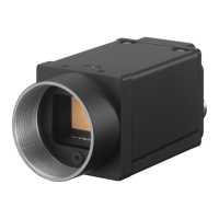
Illustrates and describes the parts on the front, top, and bottom of the camera module.
Instructions for mounting the camera module using a tripod adaptor.
Details the 12-pin DC power input connector and its pin configuration.
Explains the 26-pin mini connector for Camera Link communication and signals.
Describes the function of the green status LED on the camera.
Step-by-step guide for connecting camera and Camera Link cables.
Explains how to control the camera from a host device via commands.
Guidance on mounting the camera to a metallic base for effective heat dissipation.
Details serial port communication settings like Baud rate, Data bit, Parity, and commands.
Explains selection of Camera Link tap and clock frequency for output.
Shows combinations of camera link taps and output bit lengths/functions.
Illustrates the data order for image transmission using 1-tap configuration.
Illustrates the data order for image transmission using 2-tap configuration.
Illustrates the data order for image transmission using 3-tap configuration.
Details the Bayer Array output based on Reverse X and Reverse Y settings.
Explains input sources for trigger signals via connector pins or software command.
Defines positive and negative trigger signal polarities and their activation.
Details the circuit specifications for General Purpose Inputs (GPI).
Details the circuit specifications for General Purpose Outputs (GPO).
Describes configuring partial scan for area selection to achieve high-speed reading.
Explains adding pixels vertically or horizontally to increase frame rate and sensitivity.
Details toggling between 8, 10, or 12-bit output for monochrome and color cameras.
Explains how to flip the image vertically and horizontally.
Details setting manual gain in 0.1dB increments, including FINE settings.
Describes automatic gain adjustment based on image pickup environment and AGC levels.
Explains setting shutter time in µs units, prioritizing image quality or speed.
Details automatic shutter setting based on output level and AGC-LEVEL.
Explains how AGC and AE coordinate to adjust image levels automatically.
Describes camera operation without a trigger (free run) and with trigger signals.
Explains trigger edge detection and trigger width detection methods for exposure control.
Details enabling special trigger for continuous image pickup in different conditions.
Explains defining the source and polarity for special trigger signals.
Describes bulk and sequential modes for taking multiple images with trigger signals.
Explains repeating single or dual exposure times with one trigger signal.
Illustrates the states of trigger modes and their interrelations.
Details input sources for trigger signals for special and trigger mode operations.
Explains disabling trigger input to prevent false operations in multi-camera environments.
Describes delaying the trigger signal by a specified time.
Details counting accepted triggers and output frames.
Explains accepting trigger signals within a set width to filter noise and select cameras.
Describes immediate exposure start upon trigger detection in fast mode.
Details automatic frame rate adjustment in free-run operation based on shutter and scan settings.
Explains setting a specific video output frame rate in free-run operation.
Describes how to display the current frame rate during auto frame rate operation.
Shows fastest frame rates for partial scanning based on HEIGHT and clock settings.
Explains automatic and manual white balance adjustment methods.
Describes changing the binarization threshold for image processing.
Details changing output points for linear interpolation between input points.
Explains setting arbitrary output values for input values in the LUT.
Command to save LUT settings after changes.
Explains applying a 3x3 area filter for noise reduction, edge adjustment, or outline extraction.
Describes setting monochrome or color test charts for monochrome and color cameras.
Details checking input signals using the GPI command and pin status.
Explains transmitting signals via GPO outputs and determining output polarity.
Illustrates the system diagram for GPO1 output signals and their logic.
Shows the factory settings for GPO1, GPO2, and GPO3.
Describes the signal indicating exposure completion and video output sequence.
Explains generating pulse waveforms from the GPO connector.
Details the function of the status LED on the rear panel and its settings.
Describes reading the camera's internal temperature with accuracy.
Provides a step-by-step procedure for setting up clear and opaque defect point correction.
Explains peak and average detection modes for adjusting shading correction.
Details saving and loading shading patterns for user settings.
Outlines the procedure for fixing lighting, adjusting exposure, and executing shading detection.
Explains specifying the color pixel for shading detection on color cameras.
Describes saving main set values to channels 1-16 for user configurations.
Details managing free memory areas and assigning unique User IDs to cameras.
Explains determining startup settings using USERSET-DEFAULT and loading user sets.
Describes restoring camera settings to factory defaults and formatting settings.
Explains reading camera model, firmware version, and other information.
Details how to use the HELP command to display command lists and details.
Explains the syntax for inputting commands and parameters with examples.
Describes the camera's echo back mechanism and status responses.
Explains saving/loading commands to/from UserSet and device reset functionality.
Details the CMOS image sensor, video output size, and frame rates.
Covers operating temperature, humidity, storage, MTBF, and dimensions.
Provides minimum illumination and sensitivity values for different models.
Illustrates horizontal timing signals and parameters based on clock and tap settings.
Shows vertical timing signals and parameters related to camera link tap.
Lists the time values from trigger acceptance to exposure start.
Presents the relative response of the XCL-CG510 sensor across different wavelengths.
Shows the relative response for R, G, B, and Brightness for the XCL-CG510C sensor.
Provides detailed mechanical dimensions of the camera module in mm and inches.
Sony reserves the right to change specifications and disclaims liability for intellectual property infringements.
| Sensor Type | CMOS |
|---|---|
| Frame Rate | 60 fps |
| Interface | GigE Vision |
| Frame Rate (at full resolution) | 60 fps |
| Lens Mount | C-mount |
| Pixel Size | 3.45 µm |
| Pixel Bit Depth | 12-bit |
| Output Format | Mono8, Mono12 |
| Connectivity | Gigabit Ethernet |