EasyManua.ls Logo

Sony XM-2200GTX Service Manual

Sony XM-2200GTX
32 pages
To Next Page IconTo Next Page
Page #1 background imageLoading...
Page #1 background image
1
SERVICE MANUAL
US Model
Canadian Model
AEP Model
UK Model
E Model
XM-2200GTX
STEREO POWER AMPLIFIER
Other Specifications
Circuit system OTL (output transformerless) circuit
Pulse power supply
Inputs RCA pin jacks
High level input connector
Outputs Speaker terminals
Through out pin jacks
Suitable speaker impedance
2 – 8 (stereo)
4 – 8 (when used as a bridging amplifier)
Maximum outputs 400 W × 2 (at 4 )
600 W × 2 (at 2 )
1,200 W (monaural) at 4
Rated outputs (supply voltage at 14.4 V)
200 W × 2 (20 Hz – 20 kHz, 0.1% THD,
at 4 )
250 W × 2 (20 Hz – 20 kHz, 0.15% THD,
at 2 )
500 W (monaural) (20 Hz – 20 kHz, 0.15% THD,
at 4 )
Frequency response 5 Hz – 50 kHz ( dB)
Input level adjustment range
0.3 – 6.0 V (RCA pin jacks)
1.2 – 12.0 V (High level input)
Low-pass filter 50 – 300 Hz, –12 dB/oct
Low boost 0 – 10 dB (40 Hz)
Power requirements 12 V DC car battery
(negative ground)
Power supply voltage 10.5 – 16 V
Current drain at rated output : 48 A (at 4 )
Remote input : 1 mA
Dimensions Approx. 400 × 55 × 276 mm
(15
3/4 × 2 1/4 × 10 7/8 in.)
(w/h/d) not incl. projecting parts and controls
Mass Approx. 4.6 kg (10 lb. 6 oz.) not incl. accessories
Supplied accessories Mounting screws (4)
High level input cord (1)
Protection cap (1)
Design and specifications are subject to change without
notice.
SPECIFICATIONS
AUDIO POWER SPECIFICATIONS (US MODEL)
POWER OUTPUT AND TOTAL HARMONIC DISTORTION
200 watts per channel minimum continuous average power into
4 ohms, both channels driven from 20 Hz to 20 kHz with no more
than 0.1% total harmonic distortion per Car Audio Ad Hoc
Committee standards.
+0
–3
Ver. 1.3 2005. 05
9-961-370-04
2005E04-1
© 2005. 05
Sony Corporation
e Vehicle Group
Published by Sony Engineering Corporation
w
w
w
.
x
i
a
o
y
u
1
6
3
.
c
o
m
Q
Q
3
7
6
3
1
5
1
5
0
9
9
2
8
9
4
2
9
8
T
E
L
1
3
9
4
2
2
9
6
5
1
3
9
9
2
8
9
4
2
9
8
0
5
1
5
1
3
6
7
3
Q
Q
TEL 13942296513 QQ 376315150 892498299
http://www.xiaoyu163.com
Question and Answer IconNeed help?

Do you have a question about the Sony XM-2200GTX and is the answer not in the manual?

Sony XM-2200GTX Specifications

General IconGeneral
Channels2
Power at 4 Ohms200W x 2
Power at 2 Ohms300W x 2
Bridged Power at 4 Ohms600W x 1
Signal-to-Noise Ratio100 dB
Input Sensitivity0.3V - 6V
Crossover Frequency50-300Hz
Frequency Response5 Hz - 50 kHz

Summary

Specifications

Audio Power Specifications (US Model)

Details power output and total harmonic distortion per standards.

Other Specifications

Covers circuit system, inputs, outputs, impedance, and maximum outputs.

Section 1 General

Features

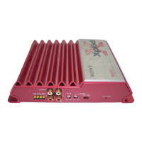
Lists key features of the amplifier.

Location and Function of Controls

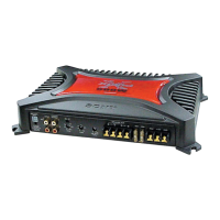
Explains the purpose of each control and indicator on the unit.

Connections

2-Speaker System

Illustrates how to connect the amplifier to a 2-speaker system.

As a Monaural Amplifier

Shows connection for using the unit as a monaural amplifier.

Power Connection Wires

Details the procedure and precautions for connecting power wires.

Monaural Amplifier for Subwoofer

Explains monaural connection for a subwoofer.

System Configurations

2-Way System

Shows output connections for a 2-way system.

Dual Mode System (Bridged Subwoofer)

Illustrates dual mode connection with a bridged subwoofer.

Four Output Channels

Details output connections for a four-channel system.

High Level Input for Monaural Subwoofer

Explains high-level input connection for monaural subwoofer use.

High Level Input Connections

High Level Input: 2-Speaker System

Shows high-level input for 2-speaker system connection.

High Level Input: Monaural Amplifier

Shows high-level input for monaural amplifier connection.

Disassembly Procedure

Bottom Plate Disassembly

Details the steps for disassembling the bottom plate.

Main Board Section Disassembly

Shows how to access the main board section for disassembly.

Main Board Disassembly

Details the disassembly procedure for the main board.

LED Board Disassembly

Details the disassembly procedure for the LED board.

Electrical Adjustment

Bias Adjustment Procedure

Explains the procedure for adjusting the bias.

Diagrams and Schematics

Block Diagram

Provides a high-level block diagram of the unit's functions.

Schematic Diagram - Main Section (1/2)

Presents the first part of the main schematic diagram.

Schematic Diagram - Main Section (2/2)

Presents the second part of the main schematic diagram.

Component Locations and Diagrams

Semiconductor Location (Main Board)

Lists semiconductor component locations on the main board.

IC Block Diagram

Shows the block diagram for IC901.

Exploded Views

Heat Sink (Main) Section

Exploded view of the heat sink and related parts.

Main Board Section

Exploded view of the main board and its components.

Electrical Parts List

Semiconductors

Lists semiconductor components with part numbers and descriptions.

Capacitors

Lists capacitor components with part numbers and specifications.

Diodes

Lists diode components with part numbers and descriptions.

Connectors

Lists connector components with part numbers and descriptions.

Jumper Resistors

Lists jumper resistor components with part numbers.

Coils

Lists coil components with part numbers and specifications.

Positive Thermistors

Lists positive thermistor components.

Transistors

Lists transistor components with part numbers and descriptions.

Resistors

Lists resistor components with part numbers and specifications.

Parts for Installation and Connections

Lists parts required for installation and connections.

Variable Resistors

Lists variable resistor components.

Cermet Resistors

Lists cermet resistor components.

Switches

Lists switch components.

Transformers

Lists transformer components.

Negative Thermistors

Lists negative thermistor components.

Accessories

Lists included accessories like manuals.

Revision Supplement

Main Board Part Number Change

Identifies changes in the main board part number.

LED Board Part Number Change

Identifies changes in the LED board part number.

Printed Wiring Boards

Main Section Layout

Shows the layout of printed wiring boards for the main section.

Schematic Diagrams

Main Section (1/2)

Presents the first part of the main schematic diagram.

Main Section (2/2)

Presents the second part of the main schematic diagram.

Revision History

Revisions Log

Lists past revisions of the service manual.

Related product manuals