EasyManua.ls Logo

Sony XM-502X User Manual

Sony XM-502X
20 pages
To Next Page IconTo Next Page
Page #1 background imageLoading...
Page #1 background image
US Model
Canadian Model
AEP Model
UK Model
E Model
STEREO POWER AMPLIFIER
XM-502X
SERVICE MANUAL
Circuit system OTL (output transformerless) circuit
Pulse power supply
Inputs RCA pin jacks
High level input connector
Outputs Speaker terminals
Through out pin jacks
Speaker impedance 2 - 8 ohms (stereo)
4 - 8 ohms (when used as a bridging
amplifier)
Maximum outputs 100 watts per channel (at 4 ohms)
260 watts (monaural) at 4 ohms
Rated outputs (supply voltage at 14.4 V)
50 watts per channel (20 Hz -
20 kHz, 0.04 % THD, at 4 ohms)
65 watts per channel (20 Hz -
20 kHz, 0.1 % THD, at 2 ohms)
130 watts (monaural) (20 Hz -
20 kHz, 0.1 % THD, at 4 ohms)
Frequency response 5 Hz - 100 kHz ( dB)
Harmonic distortion 0.005 % or less
(at 1 kHz, 4 ohms)
Input level adjustment range
0.2 - 4.0 V (RCA pin jacks)
0.4 - 8.0 V (High level input)
SPECIFICATIONS
High-pass filter 50 - 200 Hz, –12 dB/oct
Low-pass filter 50 - 200 Hz, –12 dB/oct
Low boost 0 - 10 dB (40 Hz)
Power requirements 12 V DC car battery
(negative ground)
Power supply voltage 10.5 - 16 V
Current drain at rated output: 15 A
Remote input: 2 mA
Dimensions Approx. 258 × 55 × 182 mm
(10 1/4 × 2 3/8 × 7 1/4 in.)
(l/h/p) not incl. projecting parts and
controls
Mass Approx. 1.9 kg (4 lb. 3 oz.)
not incl. accessories
Supplied accessories Mounting screws (4)
High level input cord (1)
Protect cover (1)
Design and specifications are subject to change without
notice.
+0
–3
Ver 1.1 2001. 08
Sony Corporation
e Vehicle Company
Shinagawa Tec Service Manual Production Group
9-925-591-12
2001H0400-1
© 2001. 8
Question and Answer IconNeed help?

Do you have a question about the Sony XM-502X and is the answer not in the manual?

Sony XM-502X Specifications

General IconGeneral
Channels2
RMS Power at 4 Ohms50W x 2
RMS Power at 2 Ohms65W x 2
Bridged RMS Power at 4 Ohms130W x 1
Signal-to-Noise Ratio100 dB
Speaker Level InputsYes
Frequency Response5 Hz - 50 kHz
Weight2.2 kg

Summary

Specifications

Power Requirements

Details power supply voltage and current drain.

Input/Output Specifications

Covers input level range, frequency response, and distortion.

Filter Settings

Describes filter controls and low boost.

Controls and Indicators

Level Indicators

Shows output levels and protection status.

Adjustment Controls

Covers LOW-BOOST, FILTER, and LEVEL adjustment controls.

DIRECT Switch Function

Bypasses filters and low boost for direct signal path.

Connection Diagrams

2-Speaker and Monaural Wiring

Illustrates 2-speaker and monaural amplifier setups.

Subwoofer and 2-Way Wiring

Shows subwoofer and 2-way system wiring configurations.

High Level Input Connections

Illustrates high-level input connections for various setups.

Disassembly Procedures

Bottom Plate and Front Panel Removal

Steps to remove the bottom plate and front panel.

Board Removal

Steps for removing the amplifier and filter boards.

Diagrams and Schematics

Block Diagram

Illustrates the overall functional blocks of the amplifier.

Printed Wiring Boards

Shows the layout of components on the printed circuit boards.

Schematic Diagram

Detailed electronic schematic of the amplifier circuits.

Exploded Views

Amplifier Board Exploded View

Detailed exploded view of the amplifier board components.

Filter Board Exploded View

Detailed exploded view of the filter board components.

Electrical Parts List - Amplifier

Amplifier Capacitors, Diodes, ICs

Lists capacitors, diodes, and ICs for the amplifier.

Amplifier Transistors and Resistors

Lists transistors and resistors for the amplifier.

Amplifier Other Components

Lists jumper resistors, coils, thermistors, etc. for the amplifier.

Electrical Parts List - Filter Board

Filter Board Capacitors, Diodes, ICs

Lists capacitors, diodes, and ICs for the filter board.

Filter Board Transistors and Resistors

Lists transistors and resistors for the filter board.

Filter Board Switches and Accessories

Lists switches, fuses, and accessories for the filter board.

Hardware List

Screws

Lists all screws used in the unit with part numbers.

Supplement - Difference Parts List

Panel and Heat Sink Differences

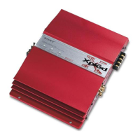
Details differences in panel and heat sink parts.

Cover and Plate Differences

Details differences in cover and ornamental plate parts.

Revision History

Version 1.1 Update Details

Notes the inclusion of CORRECTION-1 into Ver 1.1.

Version 1.0 Release

Marks the initial release of the manual.

Related product manuals