EasyManua.ls Logo

Sony XM-N502 Service Manual

Sony XM-N502
18 pages
To Next Page IconTo Next Page
Page #1 background imageLoading...
Page #1 background image
SERVICE MANUAL
Sony Corporation
Published by Sony Techno Create Corporation
XM-N502
SPECIFICATIONS
STEREO POWER AMPLIFIER
9-893-785-01
2013G33-1
©
2013.07
Canadian Model
AEP Model
UK Model
E Model
Ver. 1.0 2013.07
Circuit system OTL (output transformerless)
circuit
Pulse power supply
Inputs RCA pin jacks
Input level adjustment range
0.3 – 6 V (RCA pin jacks)
Outputs Speaker terminals
Speaker impedance
2 – 8 Ω (stereo)
4 – 8 Ω (when used as a bridging
amplifier)
Maximum output
Rated output
(supply voltage at 14.4 V, 20 Hz – 20 kHz, 1 % THD)
Frequency response
5 Hz – 50 kHz (
dB)
Harmonic distortion
0.05 % or less (at 1 kHz, 4 Ω)
Low-pass filter 80 Hz, 18 dB/oct
Power requirements
12 V DC car battery
(negative ground)
Power supply voltage
10.5 – 16 V
at rated output: 15 A
(4 Ω, 65 W × 2)
Remote input: 1 mA
Dimensions Approx. 271 × 55 × 185 mm
(w/h/d) not incl. projecting parts
and controls
Mass Approx. 1.5 kg not incl.
accessories
Supplied accessories
Mounting screws (4)
Protection cap (1)
Design and specifications are subject to change
without notice.
High level input connector
(E and Indian models only)
2.8 – 12 V (High level input)
High level input cord (1)
(E and Indian models only)
150 W × 2 (at 4 Ω)
500 W (BTL, at 4 Ω)
65 W × 2 (at 4 Ω)
85 W × 2 (at 2 Ω)
175 W (BTL, at 4 Ω)
NOTES ON CHIP COMPONENT REPLACEMENT
Never reuse a disconnected chip component.
Notice that the minus side of a tantalum capacitor may be dam-
aged by heat.

Other manuals for Sony XM-N502

Question and Answer IconNeed help?

Do you have a question about the Sony XM-N502 and is the answer not in the manual?

Sony XM-N502 Specifications

General IconGeneral
RMS output power (max)500 W
Connector contacts platingGold
Signal-to-Noise Ratio (SNR)100 dB
Number of amplifier channels2 channels
Maximum power output per channel (2 Ohm)210 W
Maximum power output per channel (4 Ohm)150 W
Product colorBlack
Weight and Dimensions IconWeight and Dimensions
Weight1500 g

Summary

Servicing Notes

Transistor Replacement Guidance

Guidance on selecting and replacing specific transistors based on rank.

Protector Operation Checks

Procedures to verify thermal, over current, and offset protection functions.

General Information

Connection Diagrams

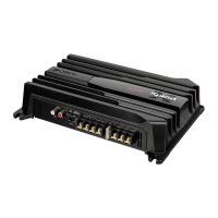
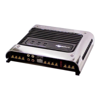
Visual guide for various input and output connections.

Disassembly Procedure

Diagram Conventions and Notes

Main Board Diagrams

Main Board Schematic Diagram (1/2)

Detailed schematic of the main board, covering the first half.

Main Board Schematic Diagram (2/2)

Detailed schematic of the main board, covering the second half.

Main Board Printed Wiring Diagram

Layout of components and traces on the main printed circuit board.

Electrical Parts List

Related product manuals