Do you have a question about the Sony XM-754HX and is the answer not in the manual?
Details minimum continuous average power output and total harmonic distortion.
Details on circuit system, inputs, outputs, speaker impedance, and other technical parameters.
Procedure to temporarily disable the protection circuit for servicing purposes.
Description of the unit's controls, indicators, and their functions.
Guidance on connecting the unit to power sources and audio equipment.
Important safety and installation guidelines to prevent damage and ensure proper operation.
Instructions for safely replacing the unit's fuse if it blows.
Details on connecting various audio input sources to the amplifier.
Guidance on connecting speaker systems for different configurations.
Procedure for removing the bottom plate, panels, and internal boards.
Procedure for adjusting the bias voltage on the amplifier board.
Overview of the amplifier's internal circuit blocks and signal flow.
Diagrams showing the layout of components on the printed circuit boards.
Detailed electrical schematic of the amplifier's circuitry.
Diagram showing the physical breakdown of the amplifier unit for parts identification.
List of key passive and active components like capacitors, resistors, and semiconductors.
List of diodes, integrated circuits, and various connector parts.
List of jumper resistors and various transistor components used in the amplifier.
List of inductor coils, pilot lamp, and other miscellaneous components.
Detailed list of transistor and resistor components with their specifications.
List of resistors, including variable resistors for adjustments and their values.
List of resistors, variable resistors, switches, and thermistors for high-level sections.
List of capacitor components used in the high-level board section.
List of connectors, resistors, and specific boards for front/rear sections.
List of hardware, screws, and instruction manuals included with the unit.
Details on differences in front panel and heat sink parts for color variations.
Details on differences in ornamental plates and rear panel parts for color variations.
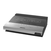
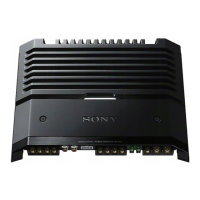
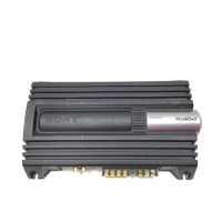
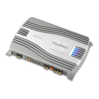
The XM-754HX is a stereo power amplifier designed for car audio systems, offering robust power output and a range of features for enhanced sound customization and protection. It is suitable for use in various car audio setups, including those with multiple speakers or bridging configurations.
The primary function of the XM-754HX is to amplify audio signals from a car audio source, delivering high-quality sound to connected speakers. It utilizes an OTL (output transformerless) circuit and a pulse power supply to ensure stable and regulated output power. The amplifier can operate in different modes to accommodate various speaker impedances and power requirements.
The XM-754HX offers several features that allow users to customize their car audio experience:
For servicing and maintenance, the XM-754HX includes a specific feature:
The XM-754HX is designed to be a reliable and high-performance stereo power amplifier, offering a rich set of features for car audio enthusiasts to achieve their desired sound quality and system configurations.
| Channels | 4 |
|---|---|
| Power Output (4 Ohms) | 75W x 4 |
| S/N Ratio | 100dB |
| Input Sensitivity | 0.2 - 4V |
| Crossover Type | HP/LP |
| Crossover Frequency Range | 50Hz - 250Hz |