7
ASSEMBLY
Drawer Assembly
(H2) (x3)
(G2) (x24)
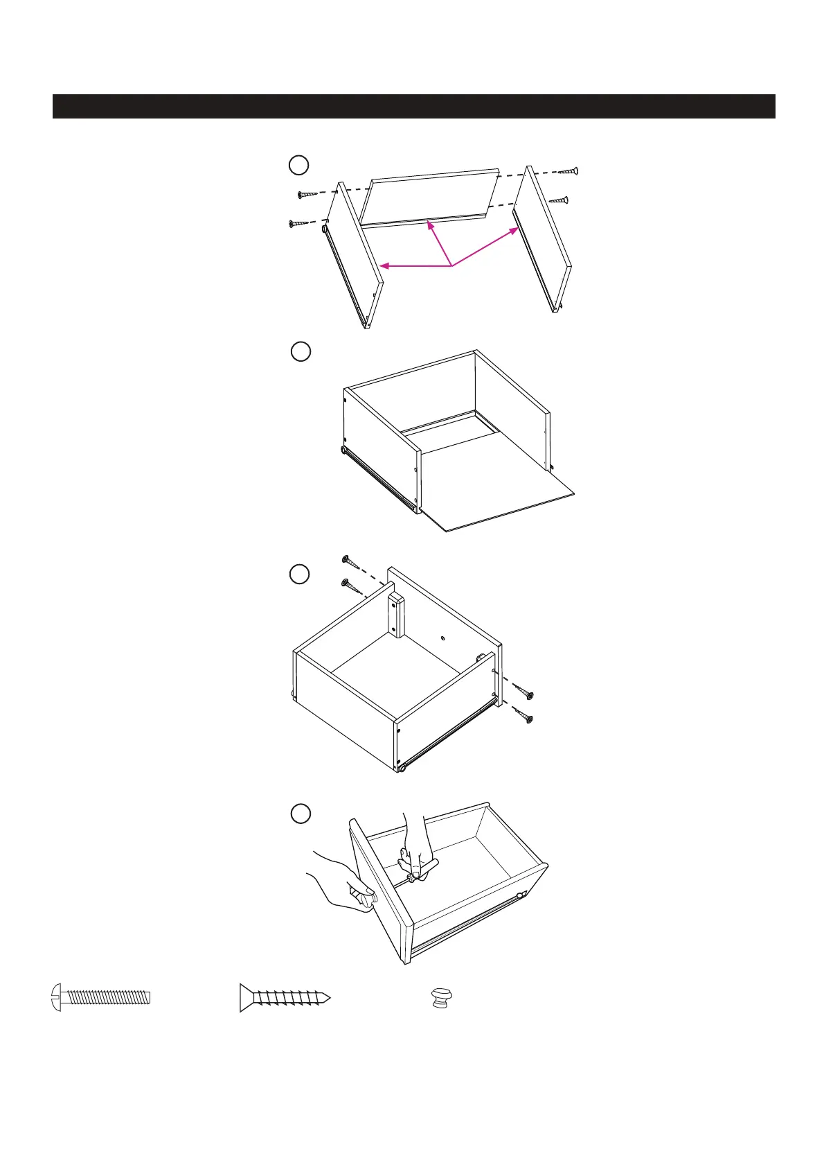
1
2
3
4
Grooves
1. Working on a padded
fl at surface, attach Drawer
Sides (C2 &D2) to Drawer
Back (B2) with Philips Head
Screw. Figure 1.
2. Slide Drawer
Bottom (A2) into drawer
assembly. Figure 2.
3. Secure both sides of
Drawer Front (F2) to drawer
assembly with four (4)
Screws (G2). Figure 3.
Check all screws for
tightness.
4. Using Drawer Knob
Screw (H2), install one (1)
Knob (E2) on Drawer.
Figure 4.
Repeat for all drawers.
Set drawers aside for
later use.
(D2)
(B2)
(A2)
Parts Needed:
Refer to pg. 6, “Drawer Parts”
(C2)
(E2)
(F2)
(G2)
(G2)
(G2)
(G2)
(H2)
(E2) (x3)