Do you have a question about the SORIN GROUP S5 System and is the answer not in the manual?
Provides basic information on maintenance and repair, and outlines the manual's structure and terminology.
Defines key terms and abbreviations used throughout the S5 System manual for clarity.
Lists standards and statutes relevant to the S5 System's development, manufacturing, and service.
Details regulations for use, general instructions, safety during use, operational, and electrical safety.
Highlights the S5 System's integrated emergency power supply (UPS) and self-test functions.
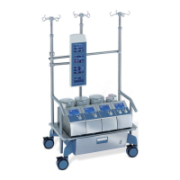
Introduces the S5 System as a modular perfusion system for controlling blood circulation.
Introduces the section detailing the physical arrangement and components of the S5 System.
Lists assemblies and components for E/P pack, pumps (RP 150, DRP 85, MRP), system panels, and sensor modules.
Presents an exploded view of the E/P pack with labeled components for assembly.
Shows an exploded view of the S5 RP 150 pump assembly with numbered parts.
Displays an exploded view of the DRP 85 pump assembly with labeled components.
Illustrates assemblies for 4, 3/6, and 5-position S5 system panels.
Displays an exploded view of various sensor modules used in the S5 System.
Shows an exploded view of the S5 MRP 150 pump assembly with labeled parts.
Illustrates the assembly of S5 MRP 85/1 and S5 MRP 85/2 pumps with numbered components.
Displays an exploded view of control panels for mast roller pumps with labeled parts.
Shows an exploded view of the Backplane E/N-Block circuit board with labeled connectors.
Displays a diagram of the motor controller circuit board with labeled sockets and components.
Shows a diagram of the motor power amplifier circuit board with labeled sockets.
Displays a diagram of the computer board with labeled sockets and components.
Shows a diagram of the inverter circuit board with labeled sockets.
Displays a diagram of the circuit board with keys and LEDs, showing labeled components.
Shows exploded views of backplane circuit boards for 4 and 5-position system panels.
Illustrates backplane circuit boards for 3- and 6-position system panels with labeled connectors.
Shows a diagram of the display and control module circuit board with labeled sockets.
Displays a diagram of the circuit board inverter for system panels and control panels.
Shows a diagram of the circuit board for fan control on mast roller pump panels.
Displays a diagram of the motor controller circuit board for MRP85 pumps.
Provides a brief overview of system menu icons and displays for general navigation.
Explains common system panel icons like menu, page, scroll, delete, cancel, and return.
Describes the "Entry displet" icon for opening parameter entry or display menus.
Details system menu icons: System menu, System icon, System message, UPS status.
Covers unspecified faults and general troubleshooting for pump, battery, and sensor module faults.
Details faults related to sensor modules and sensors, including module defective, level sensor, and signal issues.
Explains ESD measures and procedures for removing/replacing E/P pack components like boards, power supply, and batteries.
Details opening pump housing, removing pump head, control panel, touch screen, and shaft encoder.
Details how to replace the line filter on the pumps, including necessary preliminary steps.
Provides instructions for opening the pump housing of the MRP150.
Refers to another section for further disassembly of the MRP 150 pump.
Provides instructions for removing the double holder from the MRP85/x pump.
Details opening the system panel and replacing its backplane and components.
Explains when circuit board replacement is necessary and shows disconnecting connectors.
Explains how to replace circuit boards/sensor modules, noting similar exterior designs.
Covers E/P pack connectors, Phoenix, FCI, Molex, and AMP plugs/sockets.
Provides specifications for console, masts, pumps, and system panels.
Details E/P pack electrical specs, UPS/battery specs, and system panel operating parameters.
Lists specifications for pulse mode, APC, sensor modules (level, bubble, pressure, cardioplegia, temperature), and interface module.
Lists specifications for roller pump 150 and double roller pump 85, including speed, flow, and power.
Explains icons on nameplates, console, pump housing, system panel, and sensor modules.
Lists part numbers for S5 system components, mast systems, pumps, accessories, and additional devices.
Lists part numbers for E/P pack accessories, RP 150, DRP 85, system panels, and sensor modules.
Lists part numbers for console, pump spacer, and mast roller pump accessories.
Lists part numbers for various connection cables and wiring sets for system components.
Lists part numbers for mast accessories like telescope masts, push bars, horizontal masts, and retaining flanges.
Shows the overview wiring diagram for the E/P pack, illustrating connections between components.
Provides overview wiring diagrams for roller pumps (RP150, DRP85) showing connections to heads and controllers.
Shows the overview wiring diagram for the S5 system panel, illustrating connections to E/P pack and other components.
Displays the overview wiring diagram for the control panel of mast roller pumps.
| Type | Heart-Lung Machine |
|---|---|
| Intended Use | Cardiopulmonary bypass during open-heart surgery |
| Manufacturer | LivaNova (formerly Sorin Group) |
| Model | S5 |
| Application | Extracorporeal circulation during cardiac surgery |
| Pump Type | Roller pump |
| Monitoring | Pressure, temperature |
| Display | Integrated display for parameter visualization and control |
| Power Supply | 100-240 VAC, 50/60 Hz |