Page 9 / 22
Assembly instructions
Compact-Line kit
www.sorotec.de V 2.1.0
Preliminary work
Pre-assembly of the
ball screws, spindle nuts and
bearing units
Caution!
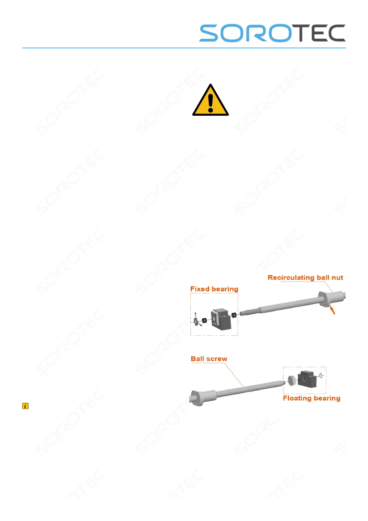
The pre-assembled recirculating ball nuts must not
be unscrewed from the recirculating ball spindles!
The ball nuts and ball screws are delicate and must
be handled with care!
In order not to damage the roller bearings during as-
sembly in the oating or xed bearing units, only the
outer bearing rings may be pressed/hit. Use a suita-
ble drive sleeve (tube) and oil the outer bearing ring
before assembly!
Install grease nipples (all drives)
• Equip all recirculating ball nuts with 90° angled
grease nipples (see gure 2, red arrow). Do not
fully tighten grease nipples yet so that you can
align them later.
Mount xed bearing (all drives)
• Push the rst bushing onto the ball screw.
• Push the xed bearing unit onto the ball screw.
• Push the second bushing onto the ball screw.
• Screw the shaft nut onto the ball screw
Attention: The collar of the shaft nut in the
direction of the xed bearing block.
• To adjust the axial play, tighten the shaft nut
until the ball screw can only be turned with
diculty in the xed bearing unit. Then carefully
loosen the shaft nut a little (approx. 5 °) until the
ball screw can easily be turned again.
• Screw the stud bolts into the threaded holes in
the shaft nut and tighten.
Install oating bearing (only X/Y drive)
• Press the roller bearing into the housing of the
oating bearing unit.
• Y-drive only: Push the oating bearing unit
onto the ball screw and attach the retaining ring
to the end of the ball screw.
Note
Floating and xed bearings are easy to distingu-
ish: the xed bearings have four mounting holes,
the oating bearings only two.
Fig. 2: Assembly of the grease nipples and spindle bearings
 Loading...