Page 10 / 22
Assembly instructions
Compact-Line kit
www.sorotec.de V 2.1.0
Assembly X axis
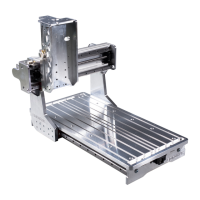
Fig. 3: Slot table with drive and guide parts
4
29
28
30
14
• Screw the linear rail
15
to the prole with
cylinder head screws M5x20
C4
uand slot 10
T-nuts M5
J1
; the reference edge of the linear
rail marked with an arrow must be in contact with
the milled stop edge of the prole over its entire
length (see Figure 4).
• Tighten the screws evenly starting in the
middle and working outwards. Tightening torque:
6 Nm
• Repeat the work steps with the second prole
and second linear rail.
Note
The sealing plugs for the holes in the guide rails
prevent the accumulation of dirt and chips, which
could otherwise damage the sealing lips of the
carriages.
• Insert the sealing plugs into the holes in the
guide rails. Make sure they sit ush.
Fig. 4: Assembly of linear rails; Note the stop edge
C4
30
15
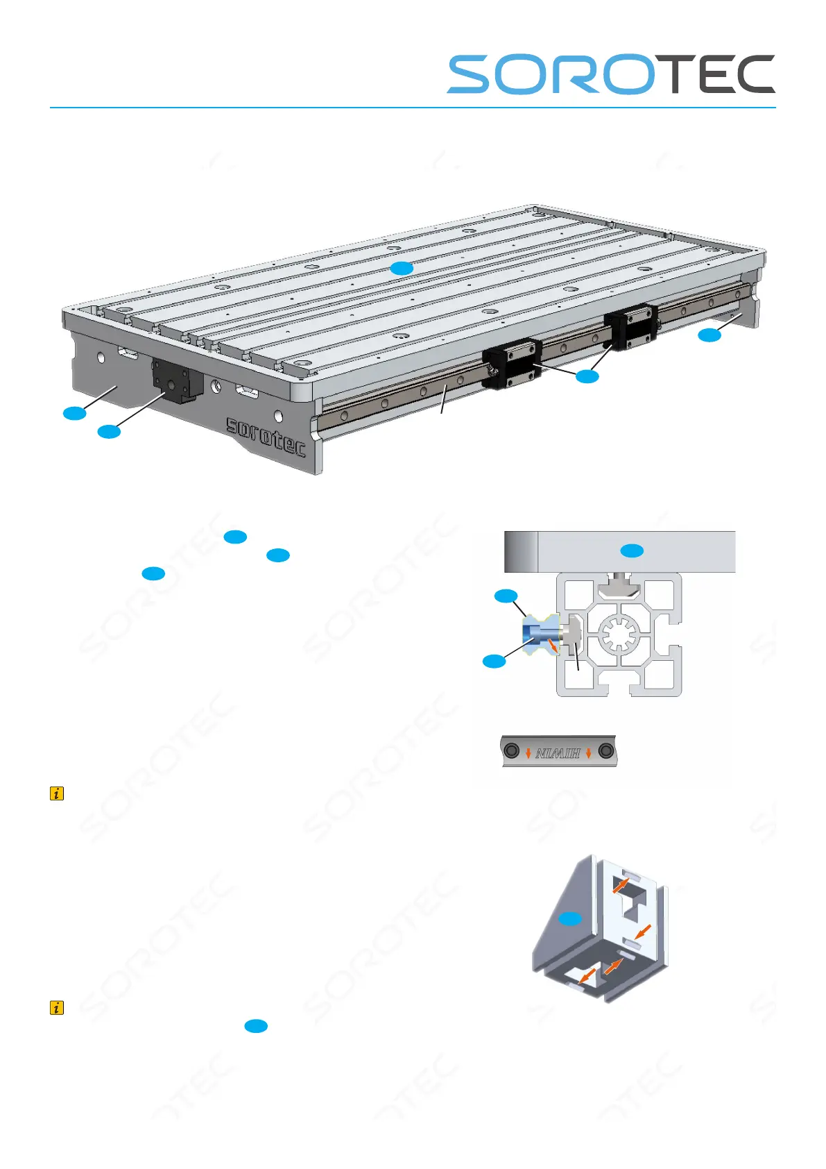
Note
When installing a bracket
32
on a component
without fastening grooves, the centering tabs on
the bracket must rst be removed (red arrows in
Figure 5). This can be done by breaking o with
a screwdriver, ling or grinding.
Fig. 5: Centering tabs on mounting bracket
32
These brackets are not installed on narrow ma-
chines with the width „03“! Accordingly, the work
steps for bracket assembly are omitted.
 Loading...