Do you have a question about the SoundCraft Spirit LX7 and is the answer not in the manual?
| Type | Analog Mixing Console |
|---|---|
| Stereo Inputs | 2 |
| Aux Sends | 4 |
| Returns | 4 |
| Subgroups | 4 |
| Phantom Power | Yes |
| Channels | 24, 32 (depending on model) |
| Mic Inputs | 24, 32 (depending on model) |
| Line Inputs | 24, 32 (depending on model) |
| EQ Bands | 3-band |
This unit must be earthed. Under no circumstances should the mains earth be disconnected.
Details the colour coding for Earth, Neutral, and Live wires in the mains lead for proper connection.
Emphasizes that the unit must be earthed and the earth connection must not be disconnected.
Instruction to replace the mains fuse only with the correct value as marked on the rear panel.
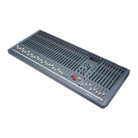
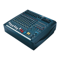
Diagram showing the main sections of the LX7 mixer, including inputs, master section, and outputs.
Illustrates how to connect microphones, instruments, and playback devices to the mixer for live sound.
Details the XLR microphone input, phantom power, and handling of unbalanced sources.
Describes the 1/4" jack input for line-level sources like keyboards and drum machines.
Explains how to adjust input sensitivity to prevent distortion or excessive noise.
Details the function of the high-pass filter to reduce unwanted bass frequencies.
Describes the unbalanced insert point for adding external signal processors.
Explains the dedicated direct output for external device connection on channels 1-16.
Allows switching direct outputs between POST-FADER and PRE-FADER modes.
Details the High Frequency (HF), Mid Frequency (MID), and Low Frequency (LF) EQ controls.
Bypasses the Equalisation section for easy comparison of equalised and unequalised signals.
Explains the use of aux sends for creating separate mixes like foldback or effects.
Adjusts the channel signal's balance between the left and right MIX buses.
Mutes all channel outputs except inserts, allowing pre-setting levels.
Provides precise balancing of various source signals mixed to the Master Section.
Describes routing channel signals to the main stereo MIX or group busses.
Allows pre-fade listening and indicates peak signal levels before clipping.
Details the high impedance stereo jack inputs for keyboards, drum machines, etc.
Sets the input level for the channel, allowing matching to various line level sources.
Controls high frequency boost or cut for adding clarity or reducing hiss.
Controls low frequency boost or cut for adding punch or reducing boominess.
Used for setting up separate mixes for foldback, effects, or recording.
Adjusts the overall signal level fed to the Mix or selected pair of Groups.
Routes the stereo channel signal to subgroups or the stereo mix.
Enables pre-fade listening of the selected signal for monitoring purposes.
Controls the master output level and AFL switch for each of the six AUX outputs.
Allows monitoring of AUX outputs after the level control by pressing the AFL switch.
LEDs that indicate power connection and correct operation of the internal power supply.
3-colour peak reading meters for monitoring subgroup and monitor/phone sources.
Routes post-fade subgroup signals in pairs to the main Mix (L/R).
Set the final output level for Subgroup and Mix L & R outputs.
Routes post-fade Mix L/R outputs to a mono bus for a separate mono mix.
Supplies 48V phantom power to all MIC inputs when the switch is activated.
Allows pre-fade listening of the selected signal for monitoring purposes.
Details the 1/4" jack for headphones and its impedance requirements.
Sets the signal level for the talkback microphone routed to aux or mix busses.
Describes the balanced stereo returns for effects units, mixed to Mix L/R busses.
Sets the level for the 2 Track Tape input, routed to headphones, monitors, or Mix outputs.
Switches Mix output to 2 Track input for pre-show music without using input channels.
Warning: Pressing this switch cuts off normal Mix L/R signal; must not be used during live performance.
Switches to select 2TK, Mono, Mix, or Groups as source for phones/monitors/meters.
Sets output level for Monitor L&R; headphone level when plugged in.
LED indicating PFL/AFL activity; shows selected source for monitors and meters.
Guide to setting initial control positions for mixer setup and performance.
Covers common problems like no power, mic issues, no signal on meters, or no output.
Checks for mains presence, connection, fuses, and single power indicator issues.
Troubleshoots 48V, mic input connection, and cable type for condenser mics.
Checks gain, source connection, inserts, faders, routing, and PFL/AFL status.
Checks master fader, 2TK REPLACES MIX switch, and monitor select.
Checks headphone jack, monitor+phones control, and monitor select.
Checks headphone impedance and monitor+phones level settings.
Illustrates typical connections for live sound reinforcement, including PA, monitors, and effects.
Shows mixer connections for churches, including PA, monitors, and induction loops.
Illustrates mixer connections for a typical studio setup with multitrack recorders.
Depicts speaker placement and delay considerations for theatre sound systems.
Diagram showing how to link two LX7 mixers for expanded functionality.
Visual representation of how audio signals flow through the mixer's internal sections.
Illustrates various balanced, unbalanced, and insert cable wiring configurations.
A printable sheet for marking and saving mixer control positions for different setups.
Details noise measurements such as EIN, output noise, and crosstalk.
Specifies the mixer's frequency response across different input types.
Total Harmonic Distortion plus Noise measurements for mic and line inputs.
Common Mode Rejection Ratio specifications for microphone inputs.
Lists the impedance values for various input and output connections.
Specifies the maximum signal levels for mic, line, stereo, and 2TK inputs/outputs.
Provides the packed weight of the mixer for different channel configurations.