Do you have a question about the SoundCraft Vi1 and is the answer not in the manual?
Essential safety guidelines and warnings for operating the Soundcraft Vi1.
Explanation of safety symbols used in the manual to alert users to potential hazards.
Guidance on proper installation procedures, including environmental and signal level considerations.
Information on safe audio practices and permissible noise exposure levels.
Details of the product warranty, coverage, and terms and conditions.
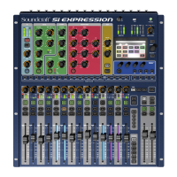
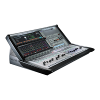
Overview of the Soundcraft Vi1 control surface and optional stage box hardware.
Detailed description of all audio, data, power, and network connectors on the rear panel.
Information about the optional stage box, its cards, and MADI connectivity.
Diagram and description of the front panel layout for the Vi6 type stage box.
Basic operational rules and conventions used within the manual for interacting with the console.
Explanation of the color coding used on the console's screens for various functions.
Description of the functionality and behavior of the Vistonics knobs and touch controls.
Explanation of how physical and touch-screen controls respond to user input.
Details on the operation modes of the Solo/Select keys.
Information on how to assign labels to channels using the on-screen keyboard.
Explanation of long and short label usage for screens and LCDs.
Guide to configuring bus types (AUX, GRP, MTX) and formats (Mono/Stereo).
Explanation of the Gang function for linking channels or busses for simultaneous control.
Diagram illustrating the signal path through the mono input channel.
Overview of the components and meters found on an input channel strip.
Description of the touch-sensitive fields for controlling input channel parameters.
Instructions on pairing input channels to create stereo configurations.
Details on the 4-band parametric equaliser, including band controls and shelf mode.
Explanation of the Gate, De-Esser, Compressor, and Limiter functions.
Guide to routing signals to AUX, Group, and Matrix busses.
Information on LR and LCR panning modes and width control.
How to set up and patch insert points for external processing on channels.
Procedure for configuring and patching direct outputs from channels.
Details on processing parameters for the Left, Right, and Centre master outputs.
How to link EQ and GEQ sections of the LRC master busses for simultaneous adjustment.
Controlling and changing parameters for the 32 output busses via the master bay.
Explanation of bus master processing shown in the input meter area.
Guide to changing parameters for output busses using input strips or other access methods.
Details on the equaliser controls for output busses, similar to input channels.
Explanation of dynamic processing (Compressor/Limiter) for output busses.
Description of PAN and Insert controls for output busses, including unique functions.
Diagram illustrating the signal flow within the matrix section.
Overview of the configurable matrix section and its capabilities.
How to adjust the contribution level of sources to a matrix output.
Steps to configure the matrix, including setting the source and patching.
Details on how channel encoders control parameters on their respective channel strips.
Explanation of the priority order for VST encoder function assignments.
How to change the function assigned to VST encoders using the Vistonics Mode panel.
Description of the dedicated panel-mounted encoders in the master section.
Information on VST encoders in the master section for output level and expanded functions.
How to use Input Fader Pages to access and overview input channels.
Accessing bus masters via master fader strips and VST areas.
Explanation of the layers and mapping for master faders in the control bay.
Accessing all 24 busses via input fader sections for quick comparison or processing changes.
Accessing all 24 bus masters through the Vistonics Output section.
How VCA and Mute Group assignments are displayed on the meter LEDs.
Description of the switches used to activate Mute Groups.
Explanation of how VCA groups behave and are controlled.
How master fader settings affect member channels in a VCA group.
Step-by-step guide for assigning channels or busses to VCA masters.
Instructions for assigning channels to Mute Group masters.
Details on using VCA groups to control Aux sends from channels.
Introduction to the patch system and its division into functional groups.
Common rules applicable to all patch pages within the console.
Guide to patching input connectors or MADI channels to input channels.
Procedure for patching a signal source to a specific input channel.
How to patch a bus or master output to physical outputs or MADI channels.
Step-by-step guide for patching bus outputs to console outputs.
Instructions for patching insert send/return pairs to input channels or master points.
Procedure for connecting a channel's direct output to an output connector.
Details on setting up direct connections between input and output connectors.
Diagram illustrating the signal flow within the monitoring section.
Overview of the three individual monitoring outputs (Monitor A, B, Headphones).
Layout and controls of the monitoring section on the master screen.
Control for trimming the solo level, context-sensitive to outputs.
Adjusts background level of monitoring source during solos.
Control for the headphone volume level.
Configuration page for solo modes (PFL/AFL/AUTO) and other monitoring settings.
Configuration options for input and output solo modes.
Sub-page for configuring output solo selection for monitors and headphones.
Explanation of the solo system, including PFL, AFL, and Solo-In-Place modes.
How input solos temporarily override output solos in monitor engineering.
Functionality to quickly identify and adjust input channels contributing to outputs.
Overview of the Talkback and Oscillator controls on the desk.
Front panel encoder for real-time control of Talkback or Oscillator levels.
Keys for routing the internal TB mic signal to various outputs.
Configuration options for the console's built-in oscillator.
How to route the TB mic signal to various outputs.
Routing inputs directly into the monitor circuit for talkback.
Description of the 10-segment level meter and 4-segment gain reduction meter.
Explanation of the gain reduction meters for bus masters.
Details on level and gain reduction meters for L, R, and C master outputs.
Description of the stereo level meter in the monitor section.
Overview of bus and input level meters displayed on the master section screen.
Information on the peak hold function available for all meters.
Options for adjusting the brightness of screens, keys, and FaderGlow.
Managing shows, including saving, loading, and exporting data.
Configuration of General Purpose Input/Output channels, available with stagebox.
Settings for clock synchronization, internal and external sources.
Details on setting up direct connections between inputs and outputs.
Access to the FX processor settings and overview pages.
Configuration for MIDI device lists, channels, and timecode settings.
General console settings including point, enable next/last, and date/time.
Overview of system hardware status and error logs.
Methods for selectively recalling parameters from snapshots: Scope and Global Filter.
Description of the snapshot control keys and their functions.
Information on the structure and display of cues, including snapshots and events.
Buttons for creating, editing, and managing cues, including multi-select operations.
Rules and methods for numbering and renumbering cues.
Graphical interface for editing and managing snapshot scope filters.
Process for copying surface settings to other cues and updating snapshots.
Functionality for isolating parameters globally or by channel strip.
Procedures for loading, saving, and managing shows via USB storage.
Explanation of which settings are recorded in shows, snapshots, and audio settings.
How to configure GPIO channels via VST fields and touch-pads.
Configuration of GPI inputs, including function, parameter, polarity, and edge.
Configuration of GPO outputs, including function, parameter, polarity, time, and edge.
Schematic diagram and electrical specifications for GPIO functionality.
Pin assignments for stage box inputs and outputs.
Introduction to FaderGlow as a status indication feature.
Table detailing FaderGlow colours for different fader operations.
Explanation of the EDIT, COPY, PASTE, and UNDO keys for data management.
Fundamental principles of copying and pasting settings between channels, busses, and FX.
How to select channels, function blocks, and parameters for copy/paste operations.
Detailed procedure for copying parameters between channels and busses.
List of parameters that are not copied when using channel or bus copy functions.
Overview of the Library system for storing and recalling settings.
Steps for browsing, editing, saving, and exporting libraries.
Procedure for copying EQ settings to the console's library.
Methods for pasting EQ settings from the library to channels.
Guide to transferring libraries between the console and USB storage.
Specifications for mixing channels, insert points, direct outputs, and busses.
Details on console and optional stage box input/output capabilities.
Overview of processing capabilities for inputs and outputs, including EQ, dynamics, and delay.
Description of the control surface layout, faders, and interfaces.
Technical specifications including frequency response, THD, noise, latency, and impedance.
Information about the 4 Lexicon effects units and their parameter control.
Details on the 27 BSS Graphic Equalizers and their assignment to busses/masters.
Accessing and adjusting all four FX processors simultaneously.
Ways to patch FX processors: channel insert, bus master insert, FX return.
Procedure for inserting an FX processor into an input channel strip.
How to insert an FX processor into an AUX Master bus for return signals.
Patching an FX processor from an AUX Master to input channels for reverb effects.
Categories and selection of FX types (Reverb, Delay, Misc).
Detailed descriptions of Reverb, Delay, and Misc effects.
Accessing and adjusting the 30 GEQ bands on the output section faders.
Mapping tables for available MIDI channels and device IDs for named devices.
Controls for parameters relating to MIDI input, including global enable.
Navigating the MIDI page to view and edit RX channel lists.
Navigating the MIDI page to view and edit TX channel lists.
Navigating the MIDI page to view and edit transmit device IDs.
Table detailing MIDI event types, their values, and Cue List TX/RX compatibility.
Overall block diagram illustrating the Soundcraft Vi1's signal flow and architecture.
| Aux Buses | 8 |
|---|---|
| Matrix Buses | 4 |
| Vistonics II Interface | Yes |
| USB Audio Interface | No |
| Sampling Rate | 48 kHz |
| Bit Depth | 24-bit |
| Digital Outputs | AES/EBU |
| Effects | Lexicon effects |
| EQ | 4-band parametric |
| Dynamic Processing | Compressors, Gates |
| Power Supply | Internal |
| Display | Vistonics II touchscreen interface |