Please see reverse for Technical Specifications
ELECTRICAL CONNECTION:
Follow diagram below for electrical
connections:
RED WIRE: Connect through a switch
and fuse to 10-16Vdc.
BLACK WIRE: Connect to a good reliable
ground (-).
PATTERN CHANGE:
Connect BLACK WIRE to ground. Touch
the WHITE WIRE to 10-16Vdc and hold
for 1-2 seconds. The mini lightbar will
advance one flash pattern and flash the
new pattern each time this is done.
INSTALLATION:
1) Determine a clean, flat location
(typically roof) on the vehicle to
mount the PINNACLE Mini Lightbar.
The PINNACLE Mini Lightbar comes
with two (2) steel brackets which
should be used to permanently
mount the light bar to a vehicle roof
or similar horizontal surface.
2) Position the bar with brackets
attached and mark hole centers.
Center punch or drill pilot holes for
a 1/4” sheet metal screw (customer
supplied).
3) Place a locking washer over the
screw and securely fasten the
brackets to the mounting surface.
The screws and holes should
be calked with a silicone based
material to prevent leakage. DO NOT
OVERTIGHTEN!
4) Make electrical connections.
Caution: Do not install this product
or route any wires in the air bag
deployment zone. Refer to your vehicle
Owner’s Manual for the location of any
air bag deployment zones.
RED BLACK
WHITE
5 AMP
FUSE
+12 Vdc
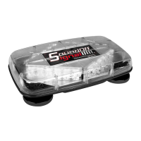
PINNACLE
LIGHTBAR
EPL7000 MINI LIGHTBAR
PERMANENT MOUNT
EPL7PD(x)C Low Bracket (shown)
EPL7HD(x)A
EPL7HD(x)C High Bracket
EPL7HD(x)A
•HIGH CURRENT interconnects must be properly terminated. Poor crimp quality can cause heat
build-up and fire. Follow crimp connector manufacturer instructions.
•DO NOT install this product or route any wires in the Air Bag Deployment Zone. Refer to vehicle
Owner’s Manual for deployment zones.
•Do NOT use system to disconnect headlights, brake lights or other safety equipment.
•Unit may become hot to touch during normal operation.
•Failure to properly install connectors, fuses or wiring may cause vehicle failure or fire.
•Installation must only be performed by trained technician. Installer must determine vehicle wiring
configuration and proper integration of system.
•Use proper wire gauge. All power wires connecting to positive (+) or negative (-) battery terminal
or local chassis ground (-) must be sized to supply at least 125% of max. current and properly fused at
power source.
•Install protective grommets when routing wire through firewall or metal.
WARNING