Do you have a question about the South N6 Series and is the answer not in the manual?
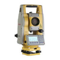
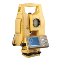
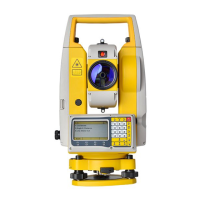
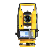
Diagram showing the parts of the total station.
Details the function of each key and information displayed on the screen.
Describes the soft keys used in different measurement modes.
How to enable and configure tilt correction for angle measurements.
Configures the instrument for different distance measurement modes.
Setting the prism constant for accurate distance measurements.
Adjusts settings for atmospheric pressure and temperature corrections.
Step-by-step guide to leveling and centering the instrument on a tripod.
Procedures for battery handling, charging, and status information.
Procedure for measuring horizontal and vertical angles.
Procedure for performing basic distance measurements.
Measuring points not directly visible using offset techniques.
General steps for measuring unknown coordinates.
Defining the instrument's position (occupied point) in the coordinate system.
Setting the instrument's position and backsight for measurements.
Measuring height without direct prism access using trigonometric principles.
Performing traverse surveys by defining start, end, and intermediate points.
Coordinate Geometry functions for calculations like intersection and MLM.
Functions for road design and stake-out operations.
Managing files: checking memory, formatting, renaming, deleting, creating.
Sending data to a computer or loading data from a computer.
Checking and adjusting the perpendicularity of the line of sight to the horizontal axis.
Adjusting vertical index difference and setting the vertical angle zero datum.
Adjusting for errors related to the transverse axis of the instrument.
| Brand | South |
|---|---|
| Model | N6 Series |
| Category | Measuring Instruments |
| Language | English |