Introduction
WARNINGS
1
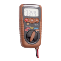
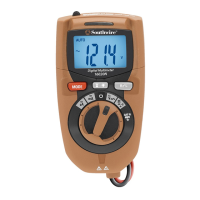
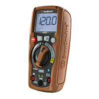
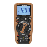
The Southwire 10020N measures AC/DC voltage and current,
resistance, frequency, and duty cycle. Other functions include
non-contact AC voltage detection, continuity and diode test.
(I\PS[PU3,+ÅHZOSPNO[VMMLYZHKKLKJVU]LUPLUJL This meter
is fully tested and calibrated and, with proper use, will provide
many years of reliable service.
9LHK\UKLYZ[HUKHUKMVSSV^[OL:HML[`9\SLZHUK6WLYH[PUN
Instructions in this manual before using this meter.
;OLTL[LY»ZZHML[`MLH[\YLZTH`UV[WYV[LJ[[OL\ZLYPMUV[
\ZLKPUHJJVYKHUJL[V[OLTHU\MHJ[\YLY»ZPUZ[Y\J[PVUZ
2LLWÄUNLYZH^H`MYVT[OLTL[HSWYVIL[PWZ^OLU[HRPUN
measurements.
)LMVYLJOHUNPUNM\UJ[PVUZ\ZPUN[OLYV[HY`M\UJ[PVUZ^P[JO
always disconnect the test leads from the circuit under test.
*VTWS`^P[OHSSZHML[`JVKLZ<ZLHWWYV]LKWLYZVUHS
WYV[LJ[P]LLX\PWTLU[^OLU^VYRPUNULHYSP]LLSLJ[YPJHS
JPYJ\P[ZWHY[PJ\SHYS`^P[OYLNHYK[VHYJÅHZOWV[LU[PHS
<ZLJH\[PVUVUSP]LJPYJ\P[Z=VS[HNLZHIV]L=(*94:
=(*WLHRVY=+*WVZLHZOVJROHaHYK
+VUV[\ZLTL[LYPM[OLTL[LYVY[LZ[SLHKZHWWLHYdamaged.
+VUV[\ZL[OLTL[LYPUH^L[VYKHTWLU]PYVUTLU[VYK\YPUN
electrical storms.
+VUV[\ZL[OLTL[LYULHYL_WSVZP]LNHZLZK\Z[VY]HWVY
+VUV[\ZL[OLTL[LYPMP[VWLYH[LZPUJVYYLJ[S`
Protection may be compromised.
+VUV[HWWS`]VS[HNLVYJ\YYLU[[OH[L_JLLKZ[OLTL[LY»Z
TH_PT\TYH[LKPUW\[SPTP[Z
2
Input Limits
Function Maximum Input
Voltage AC, Voltage DC
Frequency, Duty Cycle
Amperage µA, mA AC/DC
Resistance, Diode &
Continuity Test
600V AC/DC
600V AC/DC
Maximum Amperage 200mA,
Maximum Voltage 500V
250V AC/DC
.LULYHS:WLJPÄJH[PVUZ
Max input voltage
Diode Test
Continuity Check
Display
Over range indication
Polarity
Low Battery Indication
Input Impedance
AC Response
ACV Bandwidth
Auto Power Off
Fuse
Batteries
Operating Temperature
Storage Temperature
Operating Altitude
Size/Weight
Safety
600V AC/DC
Test current 1mA max., open circuit voltage of 1.5V typical
Audible signal if the resistance is <30Ω, sound off at >150Ω
4000 count 3 -3/4 digit LCD
LCD displays “OL”
Minus (-) sign for negative polarity
“ ” symbol indicates low battery condition
>7.5MΩ (VDC & VAC)
Average responding
45 to 450Hz
15 minutes (approximately)
mA, µA ranges; 0.2A/500V fast acting Resettable Fuse
Two 1.5V AAA
41
o
F to 104
o
F (5
o
C to 40
o
C)
14
o
F to 140
o
F (-10
o
C to 60
o
C)
7000 ft. (2000meters) maximum
4” x 2.165”x 1.28”/0.32 lb. (104x55x32.5mm/145g)
UL61010-1 CAT IV-600V Pollution Degree 2, CE Approved