5 6
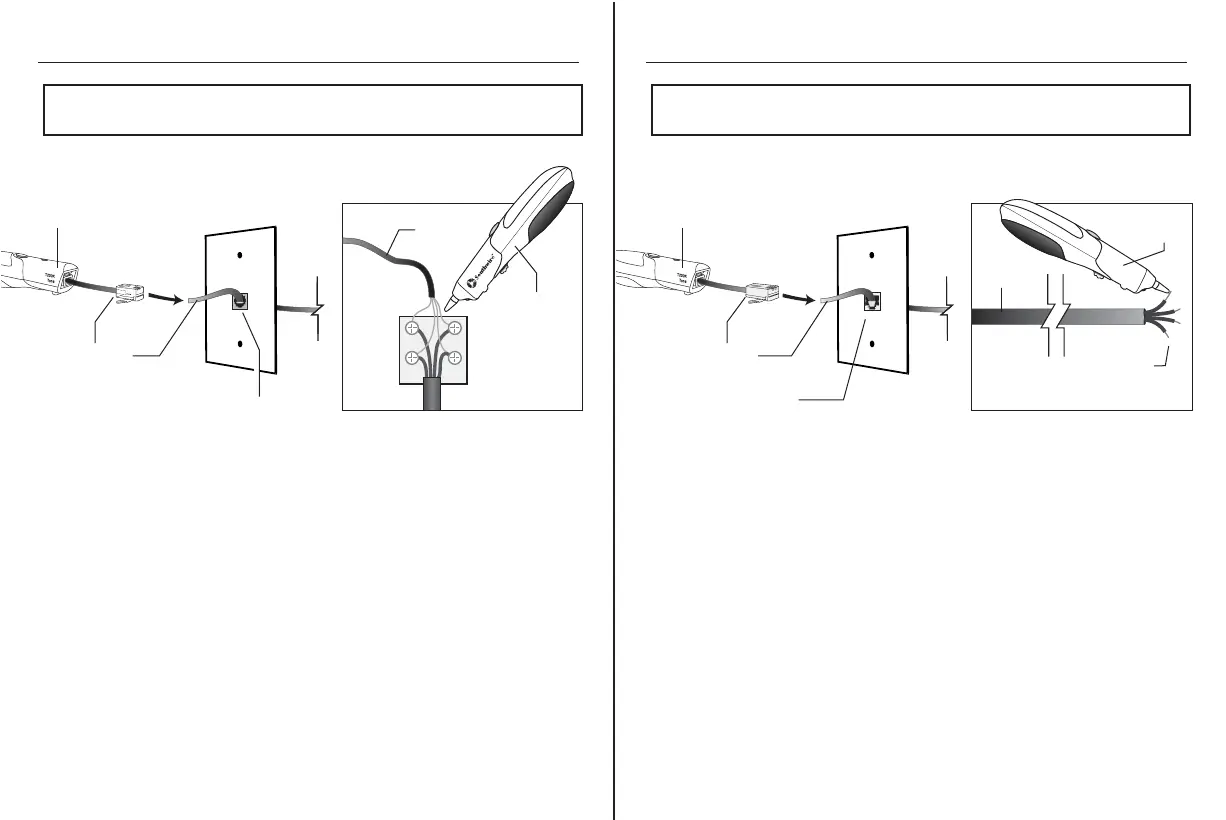
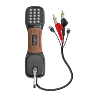
Use the Phone Adapter to connect the Transmitter to a phone jack.
The signal will be sent through pins 3 and 4 (line 1) when connected
to a 6 position phone jack.
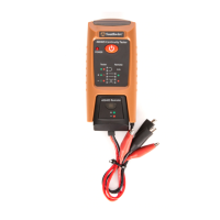
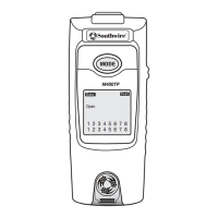
Use the Data Adapter to connect the Transmitter to a wall port or
patch panel. The tone will be sent through pins 4 and 5.
The tone will be loudest when the sensor tip is touching the
blue pair if the cable is wired to T568A or T568B standards.
To verify identification, separate the wires on the suspected pair
a few inches.
The tone should be significantly louder when to sensor tip is touching
either wire on the separated pair.
NOTE:
In order to avoid interference, disconnect the cable being tested
from the outside phone line.
Tracing Phone Cables
NOTE:
Use caution when tracing installed cable. The tone generator may
cause interference with other signals on adjacent conductors.
Tracing Data Cable
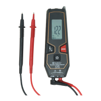
Receiver
Receiver
Phone
Cable
Phone Jack
Interior
Wires
Cable
Detail
Closeup
Phone Jack
Phone Adapter
Transmitter
Data Adapter
Wall Port
Transmitter