EasyManua.ls Logo

Soyal AR-401 - User Manual

Soyal AR-401
32 pages
Print Icon
To Next Page IconTo Next Page
Loading...
SOYAL Website Software Download
Built-in HTTP server allows direct programming through a web page using a browser,
eliminating the need for a human-machine interface.
Added unique intelligent building logic scheduling functionality, greatly simplifying
automatic management conguration for large buildings.
Standard with MOBUS-TCP to RTU Gateway and RS-485 IO expansion Port
SOYAL Operation Manual
V230825
AR-401 PLC
Programmable Logic Controller
Operation Manual
AR-401-IO-0808R-RX AR-727CM-IO-0804R
Panel PLC - DIN35 Mini PLC - DIN35
Question and Answer IconNeed help?

Do you have a question about the Soyal AR-401 and is the answer not in the manual?

Overview

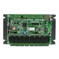
The SOYAL AR-401 PLC (Programmable Logic Controller) is a specialized device designed for smart building automation, offering cloud-based programming and extensive I/O capabilities. It is compatible with standard Modbus-TCP control syntax, making it suitable for integration into central monitoring, access control, and property management systems, especially those involving SCADA or SOYAL 701ClientSQL dynamic graphical control.

Function Description

The AR-401 PLC serves as a central control unit for automating various building functions. It allows for the creation and execution of complex logic schedules, managing digital inputs (DI) and digital outputs (DO), timers, and counters. Its core function is to provide a flexible and scalable solution for building automation, from simple on/off operations to intricate interlock systems and timed triggers.

Important Technical Specifications

Hardware:

  • Built-in I/O: The PLC itself features 8 built-in relay outputs and 8 opto-coupler inputs.
  • Expansion Capability: It can be expanded to a maximum of 256 digital inputs (DI) and 256 digital outputs (DO) through RS-485 I/O expansion communication modules.
  • Modbus Gateway: Includes one Modbus-TCP to RTU Gateway, enabling communication with RTU devices, meters, and analog interfaces.
  • Network Interface: Built-in HTTP server for web-based programming.
  • Addressing Range:
    • PLC Onboard: Inputs 000-007, Outputs 000-007, Virtual 008-015 (for AR401-0808R).
    • Node 01 (AR401-1608R): Inputs 016-031, Outputs 016-023, Virtual 023-031.
    • Node 02 (AR401-1616R): Inputs 032-047, Outputs 032-047, Virtual (none).
    • Node 03 (AR403-0404M): Inputs 048-051, Outputs 048-051, Virtual 052-063.
    • Node 04 (AR401-1608R): Inputs 064-079, Outputs 064-071, Virtual 072-079.
    • Node 05 (AR401-1608R): Inputs 080-095, Outputs 080-087, Virtual 088-095.
    • Node 06 (AR401-1608R): Inputs 096-111, Outputs 096-103, Virtual 104-111.
    • Node 07 (AR401-1608R): Inputs 112-127, Outputs 112-119, Virtual 120-127.
    • Node 08 (AR401-1608R): Inputs 128-143, Outputs 128-135, Virtual 136-143.
    • Node 09 (AR401-1608R): Inputs 144-159, Outputs 144-151, Virtual 152-159.
    • Node 10 (AR401-1608R): Inputs 160-175, Outputs 160-167, Virtual 168-175.
    • Node 11 (AR401-1608R): Inputs 176-191, Outputs 176-183, Virtual 184-191.
    • Node 12 (AR401-1608R): Inputs 192-207, Outputs 192-199, Virtual 200-207.
    • Node 13 (AR401-1608R): Inputs 208-223, Outputs 208-215, Virtual 216-223.
    • Node 14 (AR401-1608R): Inputs 224-239, Outputs 224-231, Virtual 232-239.
    • Node 15 (AR401-1608R): Inputs 240-255, Outputs 240-247, Virtual 248-255.
    • Note: The number of extension boards is inversely proportional to scanning time. For rapid response, prioritize main board I/O. For purely static monitoring, the number of extensions should not exceed 3 boards.

Logic Programming:

  • Logic Expressions: Supports 64 logic expressions via a web-based editing interface.
  • Logic Conditions: Includes "Every hour," "Every day," "Every week," "Calendar holiday," "Timer," "Counter," "AND," "OR," and "Edge event."
  • Output Types: ON/OFF, One Shot, Continue Pulse, Counter, Timer.
  • Virtual Points: Actual digital output points (DO) are shared with logical virtual points, allowing unused output points within the addressing range to be used as virtual points.
  • Timers: 8 timers available, with timing units of 0.1 or 1.0 seconds. Maximum value for a single timer is 255. Timers can be cascaded for durations up to 3000 years.
  • Counters: 8 edge-triggered counters, with a maximum value of 255 per individual count. Counters can be linked for maximum counts exceeding 100 million times.

Usage Features

Programming and Configuration:

  • Web-based Programming: A built-in HTTP server allows direct programming through a web browser, eliminating the need for a human-machine interface. This simplifies setup and management.
  • Intelligent Building Logic Scheduling: Unique functionality simplifies automatic management configuration for large buildings, including support for calendar time and holiday conditions.
  • Proactive Cloud Notification: Input point events can proactively notify the cloud monitoring system via TCP and automatically execute offline emergency linkage processes.
  • Integrated Control System: Integrates Data Center Control, Access Management, and Equipment Maintenance Shared Graphical Control System.
  • IO Schedule: A comprehensive interface to review and configure programmed schedules.
  • Schedule Setting: Offers 64 available schedules (0-63) for configuration.
    • Mode: Eight output action modes: OFF, ON, Pulse, Cycle, Toggle, TIMER, CNT Inc, CNT RST.
    • Clicks: For Pulse mode, duration from 1 to 65535 seconds. For Cycle mode, cyclic ON/OFF duration in 1-255:1-255 seconds format (e.g., 003:003 for 3 seconds ON, 3 seconds OFF).
    • Fast Click: Option to set Clicks in 0.1-second units.
    • Action Time:
      • 00:00-23:59: Triggers schedule at a fixed time daily.
      • 24:00 (default): IO trigger not time-related.
      • 24:01-24:59: Activates at a fixed minute interval every hour (e.g., 24:15 triggers at 15 minutes past every hour).
    • Holiday/Weekday Settings: Allows defining weekdays and holidays for schedule enablement.
    • Join 1-4 (Custom Trigger Conditions): Supports complex logical conditions with priority: Timer → Counter → OR → AND → Edge. Edge conditions can only be set in Join4.

Operational Examples:

  • Motor Latching Operation: Demonstrates self-holding configuration using traditional PLC ladder programming.
  • Motor On/Off Operation using Edge Trigger: Shows simplified control using edge-triggering functionality.
  • Cycle Flash Output: Example of a time-triggered cycle output (e.g., light flashing for 90 minutes on weekdays, 0.5 seconds ON, 0.2 seconds OFF).
  • Cycle Flash Output by Start Button: Control of flashing output initiated by a start button (DI7) and stopped by another (DI6), utilizing edge-triggered conditions.
  • Pulse and Toggle Output by Start Button: Demonstrates a pulse output (DO-2 for 1.5 seconds) and a toggle output (DO-3 cycling ON/OFF) using the same start button (DI6).
  • On Motor 2 minutes per hour: Activates a motor (DO-2) for 120 seconds at 01 minute past every hour.
  • Gate Alert if open more than 10 minutes with Confirm Button: A complex example using multiple schedules, timers, and counters to trigger an alarm (DO-0) if a gate (DI-0) is open for more than 10 minutes, with a virtual confirm button (DI-1) to reset the alarm.
  • DI/DO Corresponding Trigger (Enabled by Administrator for Each DO): Configures infrared devices (DI0-7) to trigger corresponding alarm indicators (DO0-7), with a virtual output (DO8-15) acting as an administrator's manual control to enable/disable the alarms.
  • Marquee Output: Creates a sequential triggering effect (DO0-6) with DO7 acting as a condition, stopping operation between 12:00 PM and 1:00 PM.
  • Four-Door Interlock: Interlocks four doors (DO0-3) such that when one door is activated, triggering of other doors from their corresponding DIs (DI0-3) is prevented.
  • Device Timed Trigger via TIMER Setting: Configures two timed outputs: a 10-second pulse output every minute and a cycle output (0.3 seconds ON/OFF loop) for 30 minutes every day at 18:00. This involves using multiple timers and counters to manage seconds, minutes, and hours.

Maintenance Features

Firmware Update:

  • Software Update: Utilizes the SOYAL Device Tools Software (SoyalToolSetup) and UDP UPDATER for firmware updates. The UDP UPDATER shortcut is automatically created upon installation.
  • Device Reading: Allows checking the controller status by entering the IP address and scanning the device, confirming normal device connection.
  • Firmware Upload: Provides a clear process to load and update firmware files, with progress indicators and completion messages ("CONTROLLER Programming Completed!").

Troubleshooting (FAQ):

  • Incorrect CNT Inc Counting: Emphasizes the importance of selecting edge-triggering conditions (^^Di or ^.Di) for accurate counter increments.
  • Timer Showing 0 After Triggering: Explains that timers reset to 0 when the trigger stops, requiring observation while the trigger is active to view the counting time.
  • Triggering Timer in a Loop: Suggests using "LESS:011" for TIMER conditions to create a 0-11 second cycle, which can then be used as a triggering condition.
  • Webpage Login Error: Provides a solution to reload specific page sections by right-clicking on the error area.

Data Management:

  • Schedule Export/Import: Allows exporting programmed schedules to a file (e.g., "Four-Door Interlock.S401") and importing them back, facilitating backup, replication, and sharing of configurations. This process involves selecting the device, reading the controller, saving/loading the file, and writing to the controller.

Soyal AR-401 Specifications

General IconGeneral
BrandSoyal
ModelAR-401
CategoryController
LanguageEnglish

Related product manuals