Do you have a question about the Soyal AR-725 and is the answer not in the manual?
Details on M3x10 screws used in installation.
Details on M3.5x15 screws used in installation.
Details on 2.5x10 screws used in installation.
Details on M3x8 screws used in installation.
Details on 4x19.1 screws used in installation.
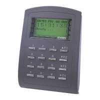
Step-by-step guide for installing the AR-725 (E-V2-M) model.
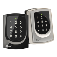
Step-by-step guide for installing the AR-725 (E-V2) model.
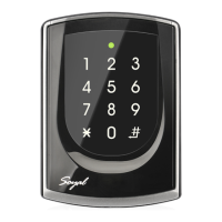
Step-by-step guide for installing the AR-725 (X) model.
Notes regarding wiring, cable selection, and power supply for the controller.
Details on wire applications, colors, and descriptions for TCP/IP output.
Details on wire applications, colors, and descriptions for RS-485 lift controller.
Details on wire applications, colors, and descriptions for lock relay.
Details on wire applications, colors, and descriptions for anti-tamper switch.
Details on wire applications, colors, and descriptions for beeper and LED.
Details on wire applications, colors, and descriptions for security trigger and arming output.
Details for optional AR-725L485 connector table.
Diagram showing connections to an electric bolt.
Diagram showing connections to a magnet lock.
Diagram showing connections to an electric strike.
Diagram illustrating security enhancement with AR-721RB.
Diagram showing connections to a door contact.
Diagram showing connections to a reader.
Wiring diagram for fire emergency door release.
Instructions for adding and deleting user tags via programming mode.
Visual representation of tag data structure (card code, site code).
Procedures for entering and exiting the device's programming mode.
Steps to change the master code for system access.
Instructions for setting the reader's node ID and door numbers.
Configuration of operational modes M4 and M8 for access control.
Procedures for setting individual user passwords for access.
How to enable and configure anti-pass-back functionality.
Configuration of auto open zones for doors.
How to configure lift access control with multiple floors.
Instructions for configuring arming modes and alarm conditions.
Procedures to reset device parameters and user data to defaults.
Steps for updating the device's firmware using the UdpUpdater software.
Guide to accessing the device's IP settings through a web browser.
Overview of the menu options within the IP setting interface.
Steps to change the device's IP address, subnet mask, and gateway.
How to set or change the password for accessing the device's settings.
Commands for entering, exiting, and changing settings in programming mode.
Commands for setting node IDs and IP addresses.
Commands to configure door and alarm relay timings.
Commands related to arming status and operational modes.
Commands for setting auto-open zones and master codes.
Commands for suspending, deleting, and managing tags and user data.
Commands for configuring output settings and user passwords.
Default values for time attendance and auto re-lock features.
Default values for auto open and exit button functions.
Default values for access modes (Card/PIN) and reader roles.
Default values for egress beep sounds and arm/disarm zones.
Default values for free access mode and alarm stop conditions.
Default values for duress functions and RS-485 communication.
| Brand | Soyal |
|---|---|
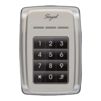
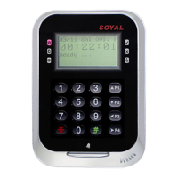
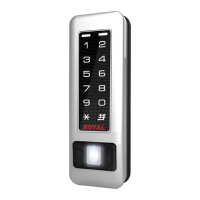
| Model | AR-725 |
| Category | Control Panel |
| Language | English |