SOYAL
ACCESS CONTROL SYSTEM
®
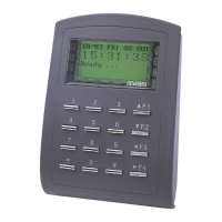
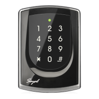
AR-327 (H) / AR-727 (H)
V140423
A. B.
A. B.
P1
P1
P2
P2
P3
P3
P4
P4
P1
P2
P3
P4
3
1
2
5
4
3
1
2
4
5
P1
P2
P3
P4
Contents
AR-327(H):Touch-panel Metal Case
AR-727 (H)
2
User Guide
2
User Guide
Installation
AR-327 (H)
AR-327 (H)
Pull the cables from the square hole of the mounting plate.
Use a screw to the mounting plate onto the wall.
Attach the water proof strip to the body, then connect the terminal cables
to the body and attach the body to the mounting plate.
Use the Allen key and screws (accessories supplied) to assemble the
body onto the mounting plate.
Turn on the power, the LED will light and hear the beep sound, you will
see "Ready"" on LCD board.
The communication wires and power line should NOT be bound in the same conduit or tubing.
Don’t equip reader and lock with the same power supply. The power for reader may be unstable when the lock is activating, that may make the
reader malfunction.
The standard installation: Lock relay and lock use the same power supply, and reader use independent power supply.
Use AWG 22-24 Shielded Twist Pair it sould avoid star wiring.
1.Tubing:
2.Wire selection:
3.Power supply:
4.F4: At rst time use, if appears no screen and green LED ashes, please press [F4] for 2 seconds.
Attach the water proof strip to the mounting plate.
Pull the cables from the square hole of the mounting plate.
Use a screwdriver to screw the base onto the wall.
Connect the terminal cables to the body and attach the body to the
mounting plate.
Assemble the covers with the Allen key and screws (accessories supplied).
Turn on the power, the LED will light and hear the beep sound, you will see
"Ready"" on LCD board.
AR-727 (H)
AR-727 (H)
1
Products
1
Products
3
Terminal Cables
3
Terminal Cables
4
Tools
4
Tools
5
Water proof Strip
5
Water proof Strip
Notice
AR-327(H) 13.56MHz Notice
Connector Table
Wire Application
Door Relay
Common-COM-Point
Door contact
Exit Switch
Alarm Relay
Power
Wire Application
Tamper Switch
Wire Application
Networking
Wiegand
Buzzer
LED
Wire Application
Arming Setting Input
Serial Port
Arming Status
indication (light)
Card existing indication
Description
(N.O.)DC24V1Amp
(N.C.)DC24V1Amp
(COM)DC24V1Amp
Negative Trigger Input
Negative Trigger Input
N.O./N.C. Options
(by jumper)
DC 12V
DC 0V
Description
N.C.
COM
N.O.
Description
RS-485 (B-)
RS-485 (A+)
WG DAT: 1 Inpu
ABA Data Input
WG DAT: 0 Input
ABA Clock Input
Buzzer Output 5V/100mA, MAX
LED Green Output 5V/20mA, MAX
LED Red Output 5V/20mA, MAX
Description
Latch type
Serial output (Transistor open
collector) (4800, N,8,1)
Arming output (Active low)/
Security trigger signal Output
Output LOW when card present
Color
Blue White
Purple White
White
Orange
Purple
Gray
Thick Red
Thick Black
Color
Red
Orange
Yellow
Color
Thick Green
Thick Blue
Blue
Green
Pink
Brown
Yellow
Color
Orange White
Yellow White
Red White
Brown White
Pin
1
2
3
4
5
6
7
8
Pin
1
2
3
Pin
1
2
3
4
5
6
7
Pin
1
2
3
4
P1Cable:
Cable:
Cable:
Cable:
P3
P2
P4
Sensing range of metal controller is small, the
proposed sensing card should step aside, do
not fully cover number keys.