EasyManua.ls Logo

SP tools SP62012 - User Manual

SP tools SP62012
13 pages
Print Icon
To Next Page IconTo Next Page
Loading...
USER MANUAL
IMPORTANT
ALL PERSONS WHO ARE TO USE THIS EQUIPMENT MUST THOROUGHLY READ
AND UNDERSTAND THIS INSTRUCTION MANUAL PRIOR TO OPERATION.
SP62012
DIGITAL
MULTIMETER
ELECTRICAL
RETAIN THESE INSTRUCTIONS
AND ATTACH RECEIPT TO
MANUAL FOR FUTURE
REFERENCE
NOTE: Proof of purchase must be retained by
the customer as it will be required in the
event of a claim under warranty.
AFTER SALES SUPPORT:
AUSTRALIA: Visit the website’s contact page to get in
touch with your local service department.
WWW.SPTOOLS.COM
INTERNATIONAL: Use the county selector to get in touch
with your service department in your country or region.
Question and Answer IconNeed help?

Do you have a question about the SP tools SP62012 and is the answer not in the manual?

Overview

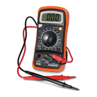
The SP62012 is a handheld 3½ digit digital multimeter designed for measuring various electrical parameters in battery-operated systems. It can measure DC and AC voltage, DC current, resistance, and also performs diode, transistor, and continuity tests.

Important Technical Specifications:

  • Maximum Voltage between terminals and earth ground: CAT II 600V
  • Fuse Protection: F 200mA/250V
  • Power Supply: 9V battery
  • Display: LCD, 1999 counts, updates 2-3 times per second
  • Measuring Method: Dual-Slope Integration A/D converter
  • Over Range Indication: Only figure "1" on the display
  • Polarity Indication: "-" displayed for negative polarity
  • Operating Environment: 0°C to 50°C
  • Storage Environment: -10°C to 50°C
  • Low Battery Indicator: "Battery symbol" appears on display
  • Size: 138mm x 69mm x 31mm
  • Weight: Approx. 170g

DC Voltage Measurement:

  • Ranges: 200mV, 2V, 20V, 200V, 600V
  • Resolutions: 100µV, 1mV, 10mV, 100mV, 1V respectively
  • Accuracy: ±0.5% of rdg + 2 digits for 200mV to 200V ranges; ±0.8% of rdg + 2 digits for 600V range
  • Overload Protection: 250V rms for 200mV range, and 600V dc or rms AC for other ranges.

DC Current Measurement:

  • Ranges: 200µA, 2mA, 20mA, 200mA, 10A
  • Resolutions: 0.1µA, 1µA, 10µA, 100µA, 10mA respectively
  • Accuracy: ±1% of rdg + 2 digits for 200µA and 2mA; ±1% of rdg + 2 digits for 20mA; ±1.5% of rdg + 2 digits for 200mA; ±3% of rdg + 2 digits for 10A
  • Overload Protection: F200mA/250V fuse (10A range unfused).

AC Voltage Measurement:

  • Ranges: 200V, 600V
  • Resolutions: 100mV, 1V respectively
  • Accuracy: ±1.2% of rdg + 10 digits for both ranges
  • Overload Protection: 600V dc or rms AC for all ranges.
  • Frequency Range: 40Hz to 400Hz.
  • Response: Average responding, calibrated in rms of a sine wave.

Diode & Continuity Test:

  • Continuity: If continuity exists (less than 1.5kΩ), a built-in buzzer will sound.
  • Diode Test: Shows the approximate forward voltage drop of the diode.
  • Overload Protection: 250Vdc or rms AC.

Resistance Measurement:

  • Ranges: 200Ω, 2kΩ, 20kΩ, 200kΩ, 2MΩ
  • Resolutions: 0.1Ω, 1Ω, 10Ω, 100Ω, 1kΩ respectively
  • Accuracy: ±0.8% of rdg ± 3 digits for 200Ω; ±0.8% of rdg ± 2 digits for 2kΩ, 20kΩ, 200kΩ; ±1.0% of rdg + 2 digits for 2MΩ
  • Maximum Open Circuit Voltage: 3.2V
  • Overload Protection: 250V dc or rms AC for all ranges.

Transistor hFE Test (0-1000):

  • Test Range: 0-1000 for NPN & PNP transistors
  • Test Current: Ib=10µA
  • Test Voltage: Vce=3V

Usage Features:

  • Display: 3½ digit, 7 segments, 15mm high LCD for clear readings.
  • Back Light (option): Activates with a push button and has an auto-off function after approximately 5 seconds to conserve battery.
  • Rotary Switch: Used to select functions, desired ranges, and to turn the meter on/off.
  • Hold Button: Freezes the current reading on the display, indicated by a "H" symbol, until pressed again.
  • Input Jacks:
    • "10A" Jack: For RED test lead for 10A current measurements.
    • "COM" Jack: For BLACK (negative) test lead, common for all measurements.
    • “VΩmA” Jack: For RED (positive) test lead for voltage, resistance, and current (except 10A) measurements.

Operating Instructions:

  • DC Voltage Measurement: Connect red lead to VΩmA, black to COM. Set rotary switch to DCV. For unknown voltages, start at the highest range and reduce as needed. Connect leads across the source/load and read the LCD.
  • DC Current Measurement: For 200mA-10A, use the 10A jack for the red lead. Set rotary switch to DCA. Open the circuit, connect leads in series, and read the LCD.
  • AC Voltage Measurement: Connect red lead to VΩmA, black to COM. Set rotary switch to AVC. Connect leads across the source/load and read the LCD.
  • Resistance Measurement: Connect red lead to VΩmA, black to COM. Set rotary switch to the desired Ω range. Connect leads across the resistor and read the LCD. Ensure power is off and capacitors are discharged if measuring in-circuit.
  • Diode Test: Connect red lead to VΩmA, black to COM. Set rotary switch to the diode symbol. Connect red lead to diode anode, black to cathode. The forward voltage drop will be displayed. "1" indicates reversed connection.
  • Transistor Test: Set rotary switch to "hFE". Determine NPN/PNP type and identify emitter, base, collector leads. Insert leads into the hFE socket. Read the approximate hFE value. Attention: Remove test leads from circuits before testing transistors to avoid electrical shock.
  • Audible Continuity Test: Connect red lead to VΩmA, black to COM. Set rotary switch to the continuity symbol. Connect leads to two points of the circuit. The buzzer will sound if continuity exists.

Maintenance Features:

  • Battery & Fuse Replacement: A battery symbol on the display indicates a low battery. To replace the battery (9V) or fuse (F 200mA/250V quick acting), remove the two screws on the back of the case. Observe battery polarity. Warning: Before opening the case, ensure test leads are disconnected from all circuits. Tighten screws completely before reuse to prevent electric shock.
  • Cleaning: Do not use abrasives or solvents. Clean with a damp cloth and mild detergent only.
  • Disposal & Recycling: At the end of its life, dispose of the tool at a designated e-waste collection point to conserve natural resources and protect human health and the environment.

Safety Information:

  • Designed according to IEC-1010 concerning electronic measuring instruments with an over-voltage category (CAT II) and pollution 2.
  • Always follow safety and operating instructions.
  • Use only supplied test leads; replace with specified type if necessary.
  • Never exceed protection limits.
  • Do not touch unused terminals when connected to a circuit.
  • Do not measure voltages exceeding 600V above earth ground in CAT II installations.
  • Set range selector to the highest position for unknown values.
  • Disconnect test leads before changing functions with the rotary switch.
  • Be aware of high amplitude voltage pulses when measuring on TVs or switching power circuits.
  • Exercise caution with voltages above 60V DC or 30V AC rms; keep fingers behind probe barriers.
  • Disconnect test leads from circuits before inserting transistors for testing.
  • Never perform resistance measurements on a live circuit.

Safety Symbols:

  • Exclamation Mark: Important safety information, refer to the operating manual.
  • Lightning Bolt: Dangerous voltage may be present.
  • Earth Ground Symbol: Earth ground.
  • Double Square: Double insulation (Protection class II).
  • Fuse Symbol (200mA/250V): Fuse must be replaced with the specified rating.

SP tools SP62012 Specifications

General IconGeneral
BrandSP tools
ModelSP62012
CategoryMultimeter
LanguageEnglish