8
SHOCKER CVO
WWW.SHOCKERPAINTBALL.COM
9
PLEASE READ CAREFULLY PLEASE READ CAREFULLY
DETENTS The ball detents in the Shocker
®
CVO prevent double-
feeding and subsequent chopping of paintballs by preventing
them from rolling forward until they are pushed into the barrel
by the bolt. Optional low-prole green detents [FIG. 17D] may
be installed for better reliability with extremely large or out of
round paint.
Each detent extends into the breech under spring pressure until
it is pushed out of the way by the paintball and bolt during the
ring cycle. If a paintball is broken in the marker, or dirt is able to
get in through the feedneck, the ball detents can become stuck,
either not extending into the breech to do their job, or stuck in the
breech, blocking proper bolt movement. In either case, cleaning
the detent system is a simple process.
DETENT CLEANING With the marker unloaded and degassed,
a 5/64-inch hex key can be used to unscrew the detent cover
screws [FIG. 16]. Finger pressure against the detent from inside
the breech is enough to unseat the detent covers so they can be
removed from either side of the Shocker
®
CVO. This will allow
access to the detents [FIG. 17A] for inspection and cleaning.
Cotton or foam swabs are ideal for cleaning the small nooks in
and around the detent. In severe cases, the detent may need to
be removed from the detent cover by pulling the hooked top of
the detent hinge pin with an o-ring pick [FIG. 17B] while taking
care not to lose the detent or spring [FIG. 17C] when they are
released and lifted away. Cleaning the detent assembly is all that
is needed for routine maintenance. Do not lubricate the detent
or the detent cover screw o-ring. The o-ring must provide friction
to lock the screw in place, and grease will gum up the detent.
Care should be taken not to cross-thread or over-tighten the
detent cover screw as this may cause permanent damage to the
Shocker
®
CVO body.
The Shocker
®
CVO utilizes a spool valve design which combines
its bolt with its main exhaust valve for a system that uses few
parts for efcient performance with few possible failure points.
Occasionally the bolt system may need to be cleaned. It also
should be lubricated after each day’s use as regular maintenance.
No tools are required for this procedure.
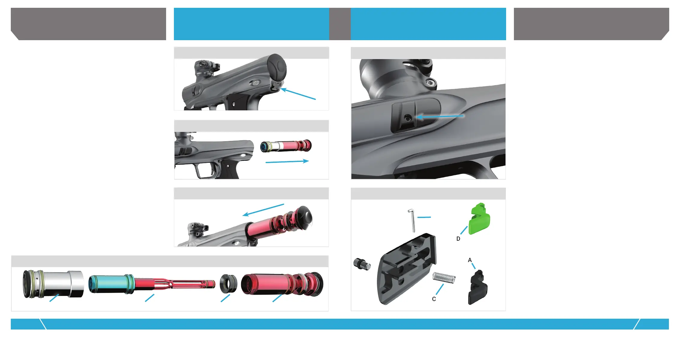
REMOVAL With the Shocker
®
CVO unloaded and degassed,
pressing on the bolt release latch [FIG. 12] will cause the end-
cap to pop out. In its extended position, the end-cap serves as a
handle to pull the entire bolt assembly from the marker body as
a single unit [FIG. 13].
CLEANING Unscrewing the ring can [FIG. 15A] from the main
chamber [FIG. 15D] provides access to the bolt [FIG. 15B] for
cleaning and inspection. All parts of the bolt assembly should
be wiped free from paint or other debris with a soft cloth. All o-rings
should be inspected for tears, at spots or other visible damage
and replaced if necessary. Before re-assembly all o-rings should
be greased lightly with GR33SE
TM
. The outer surface of the bolt’s
mid-section should also receive a very light coat of GR33SE
TM
. Oil
or other lubricants may cause damage and should not be used.
REASSEMBLY Care should be taken when re-assembling the valve
assembly. The greased parts should not be set on a dirty surface
where they will pick up dust or sand particles that can prevent
o-rings from obtaining a good seal. With the bolt placed in the
chamber guide [FIG. 15C] and the chamber guide seated in the main
chamber, the ring can should be screwed gently into place. The
complete bolt assembly can then be pushed into the body of the
Shocker
®
CVO until the latch mechanism makes an audible click,
locking everything in place with the rear cap ush against the body.
A B C D
12
RELEASE LATCH
RELEASE LATCH
16
13
BOLT ASSEMBLY REMOVAL
14
INSTALLING BOLT ASSEMBLY
15
BOLT ASSEMBLY COMPONENTS
A
B
C
D
DETENT REMOVAL
17
BOLT CLEANING
DETENTS

 Loading...