6
The larger system capacities (ESP-3642/4860J) are
affected more by higher system static pressure than the
smaller systems. Installation of the plenum tee closer
than the minimum indicated in Figure 1.4 will reduce
performance of the system. No supply runs should be
installed between unit outlet and this tee. Static
readings on system should be taken before tee.
Supply Tubing
In the case of two-story or split-level applications, supply
tubing may run from one story to another. It is small
enough to go in stud spaces, but this is often difficult in
older homes because of hidden obstructions in stud
spaces. It is more common to run the supply tubing from
the attic down through second story closets to the first
story terminators.
Supply tubing runs in the corners of the second story
rooms can be boxed in and are hardly noticeable since
overall diameter is only 3-1/4".
Room Terminators
Terminators should be located primarily in the ceiling or
floor for vertical discharge or high on a wall for horizontal
discharge. Installation of horizontally discharged terminators
is assisted with the SpacePak 90˚ wall elbow (see page 19).
Two excellent spots for horizontal discharge are in the soffit
area above kitchen cabinets (see Figure 1.5) and in the top
portion of closets (see Figure 1.6).
Terminators should always be out of normal traffic
patterns to prevent discharge air from blowing directly on
occupants. And they should not be located directly above
shelves or large pieces of furniture. Outside wall or corner
locations are recommended if the room has more than
one outside wall. Locating terminators away from interior
doors prevents short cycling of air to the return air box.
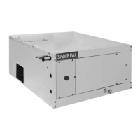
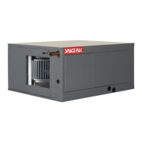
SHIPMENT OF UNIT
Each fan coil unit is shipped in a single carton. Packed with
the unit, there are vibration isolation pads, a condensate
trap assembly and a factory installed primary float switch.
Each unit comes from the factory charged with nitrogen.
When the unit is unsealed, a slight “pop” or “hissing”
noise should be heard. This guarentees that the unit is
properly sealed.
NOTICE: For high altitude systems use the following
chart as a guideline for number of outlets.
UNIT NO. 1
UNIT NO. 2
30% MAX. OF CAPACIT
 Loading...