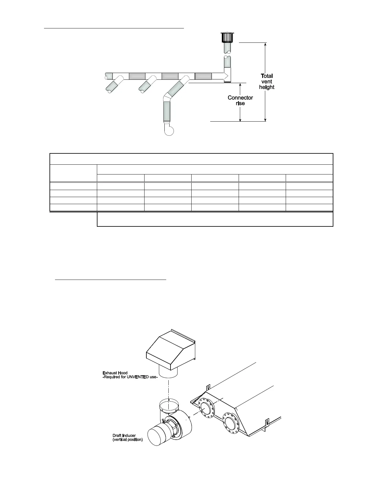
THE ABOVE ILLUSTRATIONS AND TABLE OF VENT SIZES FOR COMMON VENTING OF MULTIPLE HEATERS ARE IN
ACCORDANCE WITH THE NATIONAL FUEL GAS CODE ANSI Z223.1-LATEST EDITION, NFPA 54-LATEST EDITION, EQUIPMENT
VOLUME OF 1988 ASHRAE HANDBOOK, CURRENT CAN/CGA-B149.1/2-M86 INSTALLATION CODE, AND AGA PUBLICATION
NO. 10M5.85 2.5-2 ON FUNDAMENTALS OF GAS APPLIANCE VENTING AND VENTILATION-REVISED BUT ARE NOT A PART OF
THE CSA CERTIFICATION.
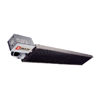
B. INDIRECT VENTING (UNVENTED HEATERS) — COMMERCIAL AND INDUSTRIAL INSTALLATIONS ONLY — This
heater requires ventilation in the building to dilute the products of combustion and provide fresh air for
efficient combustion. Where unvented heaters are used, gravity or mechanical means shall be provided to
supply and exhaust at least 4 CFM per 1,000 Btu/hr input of installed heaters. Exhaust vents must be
located at the highest point above and in the vicinity of the heaters, and the inlet vents must be located
below the level of the heaters. An exhaust hood (Part #42924000) must be placed on the outlet collar of the
draft inducer or on the existing 4” starting collar when used unvented and must be mounted only in an
upright position and directed towards the reflector body as shown.