EasyManua.ls Logo

Space-Ray LTU Series User Manual

Space-Ray LTU Series
63 pages
To Next Page IconTo Next Page
Page #1 background imageLoading...
Page #1 background image
Form #43155040
May 2013
INSTALLATION AND OPERATION INSTRUCTIONS
OWNER / INSTALLER: For your safety this manual must be carefully and thoroughly read and
understood before installing, operating or servicing this heater.
INFRARED RADIANT TUBE HEATER
Two Stage Pull Through System (Negative Pressure)
Models:
L
T
U
SERIES:
(
100,
110, 120,
125,
130, 140,
150,
160,
175, 180, 200, 225, 250) – N7/L7
L
T
S
SERIES:
(
60,
75,
100,
110, 120,
125,
130,
140, 150, 160, 175, 180, 200, 225, 250) – N7/L7
!
INS
TALLER
:
This manual is the property of the owner. Please present this manual to the
owner when you leave the job site.
▲WARNING: Improper installation, adjustment, alteration, service, or maintenance can
cause property damage, injury or death. Read the installation, operation and maintenance
instructions thoroughly before installing or servicing this equipment.
IF YOU SMELL GAS: FOR YOUR SAFETY
FOR YOUR SAFETYFOR YOUR SAFETY
FOR YOUR SAFETY
!
!!
!
DO NOT
DO NOTDO NOT
DO NOT try to light any appliance.
!
!!
! DO NOT
DO NOTDO NOT
DO NOT touch any electrical switch; DO NOT
DO NOTDO NOT
DO NOT use any
telephone in your building.
!
!!
! IMMEDIATELY
IMMEDIATELYIMMEDIATELY
IMMEDIATELY call your gas supplier from a neighbor's
telephone. Follow the gas supplier's instructions. If you
cannot reach your gas supplier, call the fire department.
DO NOT
DO NOT DO NOT
DO NOT store or use gasoline or other
store or use gasoline or other store or use gasoline or other
store or use gasoline or other
flammable vapors and liquids in the
flammable vapors and liquids in theflammable vapors and liquids in the
flammable vapors and liquids in the
vicinity of
vicinity of vicinity of
vicinity of
this or any other appliance.
this or any other appliance.this or any other appliance.
this or any other appliance.
!IMPORTANT:
!IMPORTANT:!IMPORTANT:
!IMPORTANT:
SAVE THIS MANUAL FOR FUTURE REFERENCE.
SAVE THIS MANUAL FOR FUTURE REFERENCE.SAVE THIS MANUAL FOR FUTURE REFERENCE.
SAVE THIS MANUAL FOR FUTURE REFERENCE.
SPACE
SPACESPACE
SPACE-
--
-RAY
RAYRAY
RAY
Post Office Box 36485 (28236) • 305 Doggett Street (28203) • Charlotte, North Carolina
Phone (704) 372-6391 • Fax (704) 332-5843 • www.spaceray.com • email: info@spaceray.com

Table of Contents

Question and Answer IconNeed help?

Do you have a question about the Space-Ray LTU Series and is the answer not in the manual?

Space-Ray LTU Series Specifications

General IconGeneral
ModelLTU Series
Fuel TypeNatural Gas or Propane
TypeInfrared Heater
EfficiencyUp to 92%
ThermostatOptional
WarrantyLimited Warranty (Specific terms vary, refer to manufacturer documentation)

Summary

1.0 SAFETY

2.0 INSTALLER RESPONSIBILITY

3.0 GENERAL INFORMATION

INSTALLATION REQUIREMENTS

Details on conforming to codes, clearances, and mounting for various models and applications.

4.0 MINIMUM CLEARANCES TO COMBUSTIBLES

5.0 TYPICAL SUSPENSION METHODS

6.0 LTU SERIES SPECIFICATIONS

7.0 LTU SERIES PACKING LIST

A. Control/Draft Inducer Package

Lists components included in the control and draft inducer package for LTU models.

B. LTU 80-250 Body Package Descriptions

Details body package components for LTU 80-250 models based on system length.

8.0 LTU SERIES TYPICAL LAYOUTS

8.1 LTU SERIES DIMENSIONS

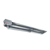
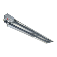
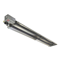
Provides diagrams and dimensions for LTU series heater models.

8.2 LTU 80-175 SERIES HEATER ASSEMBLY OVERVIEW

Overview of the assembly for LTU 80-175 series heaters.

8.3 LTU 180-250 SERIES HEATER ASSEMBLY OVERVIEW

Overview of the assembly for LTU 180-250 series heaters.

8.4 LTU SERIES 15' BODY PACKAGE OPENING

Instructions for opening the 15' body package for LTU series heaters.

8.5 LTU 80-130 SERIES HEATER ASSEMBLY

Step-by-step assembly instructions for LTU 80-130 series heaters.

8.6 LTU 125-250 SERIES – JOINING OF 5' AND 10' BODY SECTIONS

Instructions for joining 5' and 10' body sections for LTU 125-250 models.

9.0 LTS SERIES SPECIFICATIONS

10.0 LTS SERIES PACKING LIST

A. Control/Draft Inducer Package

Lists components included in the control and draft inducer package for LTS models.

B. LTS 40-200 Body Package Descriptions

Details body package components for LTS 40-200 models based on system length.

C. LTS 225-250 Body Package Descriptions

Details body package components for LTS 225-250 models based on system length.

11.0 LTS SERIES TYPICAL LAYOUTS

11.1 LTS SERIES DIMENSIONS

Provides diagrams and dimensions for LTS series heater models.

11.2 LTS 40-175 SERIES HEATER ASSEMBLY OVERVIEW

Overview of the assembly for LTS 40-175 series heaters.

11.3 LTS 180-250 SERIES HEATER ASSEMBLY OVERVIEW

Overview of the assembly for LTS 180-250 series heaters.

11.4 LTS SERIES HEATER ASSEMBLY

Step-by-step assembly instructions for LTS series heaters.

11.5 LTS SERIES - ADDING OPTIONAL 90° ELBOW

Instructions for installing an optional 90° elbow accessory.

11.6 LTS SERIES - ADDING OPTIONAL CORNER REFLECTOR

Instructions for installing an optional corner reflector accessory.

11.7 LTS SERIES - ATTACHING CONTROL BOX ASSEMBLY

Procedure for attaching the control box assembly to the heater.

11.8 LTS SERIES - ATTACHING DRAFT INDUCER ASSEMBLY

Procedure for attaching the draft inducer assembly to the heater.

11.9 LTS SERIES - INCLINED MOUNTING INSTRUCTIONS

Instructions for mounting LTS series heaters at an incline.

12.0 ACCESSORY PACKAGES

A. Elbow Accessory Package

Details of the optional elbow accessory package for LTS series.

B. Corner Reflector Accessory Package

Details of the optional corner reflector accessory package for LTS series.

C. Exhaust Hood Package

Details of the optional exhaust hood accessory package.

13.0 MULTIPLE HANGING & DRAFT INDUCER POSITIONS

14.0 GAS CONNECTIONS AND REGULATIONS

15.0 INSTRUCTIONS FOR PRESSURE TEST GAUGE CONNECTION

16.0 ELECTRICAL CONNECTIONS

FIELD CONNECTION AND THERMOSTAT WIRING DIAGRAMS

A. LOW VOLTAGE (24V) THERMOSTAT CONNECTIONS – SINGLE HEATER PER THERMOSTAT

Wiring diagrams for single heater thermostat connections.

C. MANUAL SWITCH CONNECTIONS – SINGLE HEATER OPERATION PER DUAL MANUAL SWITCH

Wiring diagrams for single heater operation with a dual manual switch.

D. MANUAL SWITCH CONNECTIONS - MULTIPLE HEATERS OPERATION PER DUAL MANUAL SWITCH

Wiring diagrams for multiple heaters operation with a dual manual switch.

17.0 VENTING

A. BASIC FLUE VENTING

General guidelines for basic flue venting, including single and multiple heater setups.

18.0 AIR FOR COMBUSTION

B. INDIRECT VENTING (UNVENTED HEATERS)

Ventilation requirements for indirect (unvented) heaters to dilute combustion products.

18.1 DIRECT OUTSIDE AIR FOR COMBUSTION

Guidelines for supplying direct outside air for combustion, especially in contaminated areas.

19.0 LIGHTING AND SHUTDOWN INSTRUCTIONS

20.0 SEQUENCE OF OPERATION

21.0 CONTROL COMPONENT LOCATION

22.0 CLEANING AND ANNUAL MAINTENANCE

23.0 TROUBLESHOOTING GUIDE

24.0 REPLACING PARTS

24.1 REMOVING SPARK ELECTRODE

Procedure for removing and inspecting the spark electrode.

24.2 REMOVING MAIN BURNER AND GAS VALVE

Procedure for removing the main burner and gas valve assembly.

24.3 AIR SWITCH PRESSURE CHECK

Instructions for checking the air switch operating pressure.

24.4 IGNITION SYSTEM CHECKS

Checks and troubleshooting for the ignition system components.

24.5 MOTOR AND BLOWER WHEEL CHECK

Troubleshooting steps for the draft inducer motor and blower wheel.

25.0 INSTALLATION DATA

26.0 REPLACEMENT PARTS GUIDE

27.0 WARNINGS CARD

Related product manuals