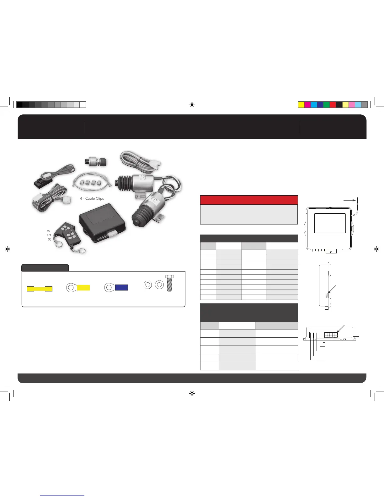
(2) Yellow 5/16”
Ring Terminals
(2) Yellow Butt
Connectors
(2) Blue Butt
Connectors
(4) 1/4” x 20 x 1 Mounting
Bolts/ Nuts/Washers
Accessories
Fu n c t i o n a l i t y :
The SHAVED-40 is designed to operate up to 7 functions. Channels 1 and 2
are controlled by 2 on-board relays (see page #2 for output locations). Chan-
nels 3 through 7 are controlled by negative output wires (see page #2
for output locations) supplied to external relays (not provided).
Fe a t u r e s :
op e r a t i o n :
1) Control module can hold up to (4) key fobs (transmitters) with different signals.
2) Control module incorporates a lock pulse timer that provides a .4 second pulse from the control
module to the device(s). If the buttons on the key fob (transmitter) are held down for an extended
period, the lock pulse timer will prevent the device(s) from being damaged.
3) Control module incoporates a time-out feature that eliminates damage to the device(s) by shutting
down the system for 30 seconds if the buttons on the key fob (transmitter) are activated more then
8 times in a 30 second period. After the 30 second time-out period, the system will function as
normal.
4) Key fob (transmitter) has a range of 150’ maximum.
10-Pi n Ma t i n g Co n n e C t o r 9357-10
CAVITY CIRCUIT WIRE COLOR FUNCTION
1 Ground Black To Ground
2 Not Used Green ---
3 Channel 7 Purple Negative Output
4 Channel 5 Blue Negative Output
5 Channel 3 Orange Negative Output
6 +12V Red To Power
7 Ignition Yellow To Ignition Power
8 Not Used Grey ---
9 Channel 6 White/Black Negative Output
10 Channel 4 Brown Negative Output
SP a d e te r M i n a l S (Po S t i o n 1 iS Cl o S e S t to
10-Pi n Co n n e C t o r ) Ma t i n g Co n n e C t o r
.250” Fe M a l e te r M i n a l
POSITION CIRCUIT WIRE COLOR
1 Not Used Violet
2 Not Used Orange
3 12V Red
4 Channel 1 Brown
5 Channel 2 Yellow
Antenna 15” Long
(Do Not Ground Or Cut)
LED (Red)
10-Pin Connector
12345
678910
1
2
3
4
5
Spade Terminals
 Loading...