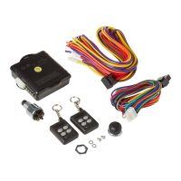
• The solenoids provided in the SHAVED40 kit can be mounted horizontally or
vertically (with the plunger UP) to the door with the provided hardware.
• Attach the solenoid to the door latch with the supplied cable and cable crimp.
-Loop the cable through the solenoid and the door latch and crimp the two ends
together with the cable crimp.
Solenoid Wiring:
• Attach the white wire of the Driver Door Solenoid to the Brown wire (large
gauge/channel 1, from spade connector harness) of the receiver.
• Attach the white wire of the Passenger Door Solenoid to the Yellow wire (large
gauge/channel 2, from spade connector harness) of the receiver
• Connect the remaining black wire of the solenoid to a ground located on the
vehicle body. (The door is not a proper grounding source!)
**A mechanical backup switch should be utilized in the case of power failure. (See the
optional wiring section)**
4
Mounting / Wiring Section
5
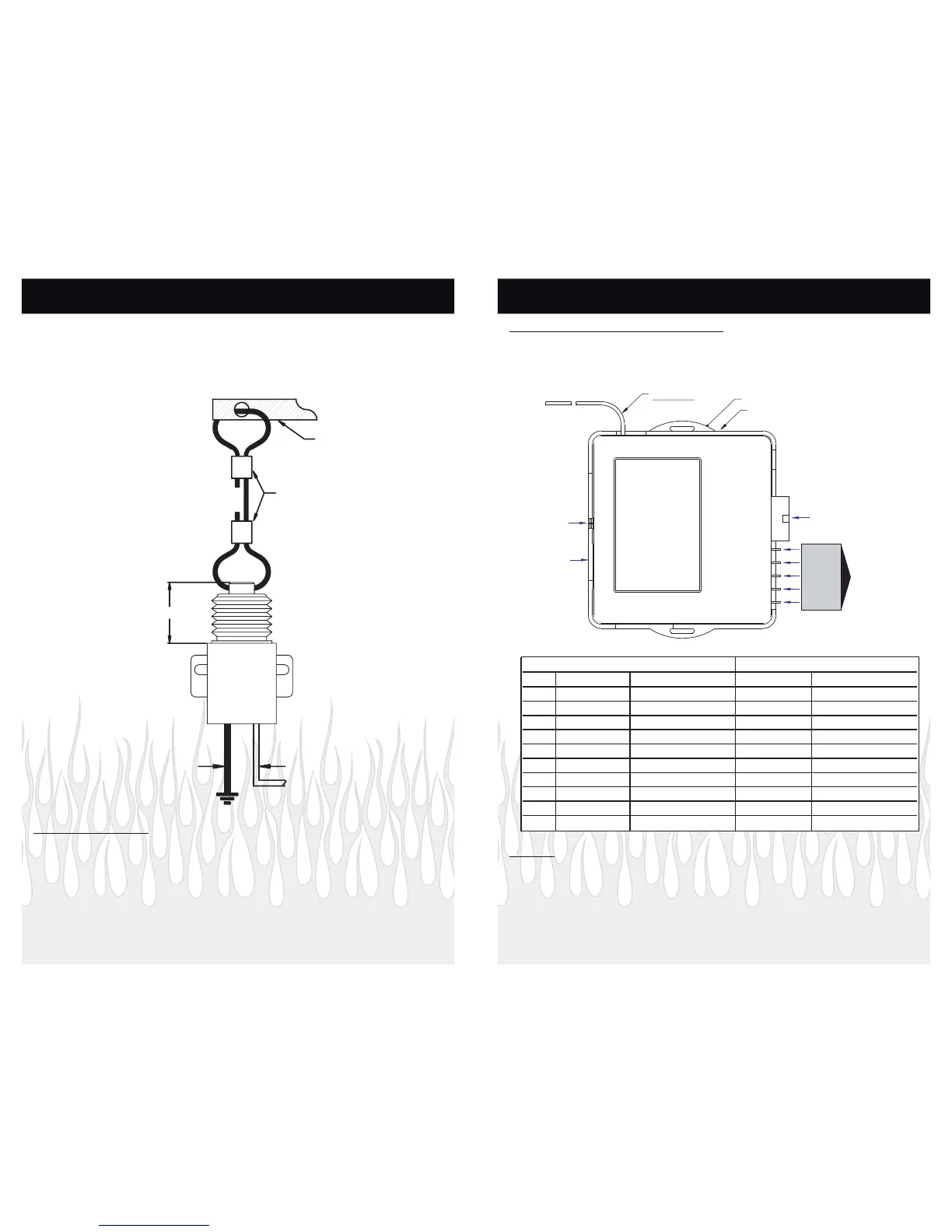
Receiver Mounting and Wiring:
**The receiver must be mounted inside the vehicle to avoid moisture**
***Do not plug in the receiver module until all the wiring is complete!***
***Do Not Ground the Antenna!***
ANTENNA
NOT USED
NOT USED
+12 VOLTS DC
CH1 OUTPUT (+)
CH2 OUTPUT (+)
SEE TABLE
DIP SWITCHES
PROGRAMMING BUTTON
LED
JUMPERS
MOLEX CONNECTOR
SPADE CONNECTORS
Notes:
*Connecting the YELLOW (ignition) wire will disable Channels 1-4 while the ignition key is ON.
**Whan installing a SHAVED ACT Kit replace the 35 Amp fuse with the supplied 10 Amp fuse
The unit will stop operating for 30 seconds if any combination of the Remote Control
Buttons 1 and/or 2 are pressed eight (8) times in 30 seconds. After 30 seconds the unit
will automatically reset to standard operating mode.
Mounting / Wiring Section
Molex Connector Spade Connectors
Pin # Wire Color Circuit Wire Color Circuit
1 Black Ground Violet Not Used
2 Not Used Not Used Orange Not Used
3 Purple Channel 7 Red Positive 12 VDC**
4Blue Channel 5 Brown Channel 1
5Orange Channel 3Yellow Channel 2
6 Red Positive 12 VDC
7Yellow Ignition*
8 Not Used Not Used
9 White/Black Channel 6
10 Brown Channel 4
 Loading...