11
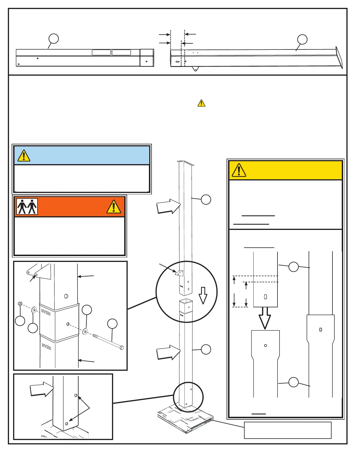
CAUTION!
WHEN PROPERLY
ASSEMBLED, THE POLE
SECTIONS SHOULD HAVE A
4” MINIMUM TO 5”
MAXIMUM OVERLAP.
5.
6.
Wood Scrap - 6” x 6” minimum
(NOT SUPPLIED)
2
3
TOP
BOTTOM
3
2
Correctly identify each pole section (TOP and BOTTOM). SEE ILLUSTRATION BELOW.
NOTE: Please disregard pole identication labels.
IMPORTANT!
NOTE ORIENTATION OF EACH POLE SECTION.
Position each pole section so that the FRONT and
REAR faces match the illustration when assembled.
SEE DETAIL VIEWS BELOW
WARNING!
TWO CAPABLE ADULTS REQUIRED
FOR THIS PROCEDURE. FAILURE
TO FOLLOW THIS WARNING COULD
RESULT IN SERIOUS INJURY AND/
OR PROPERTY DAMAGE.
REAR FACE
BOTTOM
POLE
REAR FACE
TOP
POLE
FRONT FACE
TOP POLE SECTION
FRONT FACE
BOTTOM POLE SECTION
REAR FACE
TOP
POLE
NOTE
HOLE
LOCATION
MARK
LINES
4” (10 cm)
5” (12.7 cm)
4”
5”
Use pencil or tape and mark one line at 4” and one line at 5” from top of bottom pole. ASSEMBLE TOP POLE TO
THE MARKED RANGE OF 4”TO 5”. While maintaining alignment, bounce bottom pole section (2) into top section
(3) using a wood scrap as shown. Continue until the top pole (3) has reached the marked range of 4” minimum -
5” maximum overlap of the bottom pole (2). See CAUTION! NOTE: IF MINIMUM POLE ENGAGEMENT
CANNOT BE ACHIEVED !! STOP!! DO NOT PROCEED TO THE NEXT STEP! - CALL SPALDING
CUSTOMER SERVICE FOR ASSISTANCE. When proper range of pole assembly has been achieved,
install bolt (B9), washers (B10) and nut (B11) as shown below.
2
3
NOTE
BRACKET
LOCATION
9
10
BOTTOM
POLE
TOP
POLE
11
10
NOTE
BRACKET
LOCATION
 Loading...