Do you have a question about the SPALDING U-Turn Lift System and is the answer not in the manual?
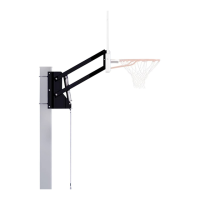
Attaching the pole bracket to a square pole using U-bolts, washers, and nuts.
Attaching the pole bracket to a round pole using U-bolts, clamps, washers, and nuts.
Securing the pole bracket to a flat solid surface with bolts and nuts.
Attaching struts, angle brackets, and jack support brackets to the pole bracket for roof mounting.
Attaching elevator tubes to jack support brackets using bolts, washers, spacers, and nuts.
Adhering the warning label in a clearly visible place on the assembly.
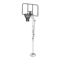
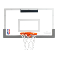
Attaching the backboard to the frame using the shown hardware.
Assembling backboard brackets, attaching the backboard, and bending support brackets.
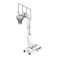
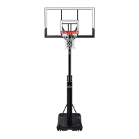
Positioning the crank and rotating the handle to adjust the backboard height.
| Backboard Material | Polycarbonate |
|---|---|
| Adjustability | Yes |
| Pole Material | Steel |
| Assembly Required | Yes |
| Material | Steel |
| Adjustment Mechanism | U-Turn Lift |
| Height Adjustment Range | 7.5 to 10 feet |
| Backboard Size | 54 inches |
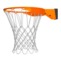
| Rim Type | Breakaway |
| Rim Size | 18 inches |