Component:
Image Reference:
LED (5mm)
+
-
+
-
c2 c3
Jumper Wire
Pin 13
e2
330Ω Resistor
a3
GND
a3
Jumper Wire
GND
Jumper Wire
5V
5V
+
“5V” on the RedBoard connects to the row marked “+” on the breadboard.
“Pin 13” on the RedBoard connects to socket “e2” on the breadboard.
“GND” on the RedBoard should be connected to the row marked “-” on the breadboard.
Resistors are placed in breadboard sockets only. The “-” symbol represents any socket in its vercal
column on the Power bus.
Breadboard: The white background
represents a connecon to a
breadboard socket specified by a
leer-number coordinate such as
e2. These coordinates are merely
suggesons that align with the
graphic image.
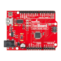
RedBoard: The red background
represents a connecon to one of
the RedBoard header pins.
Components like LEDs are inserted into the breadboard sockets c2(long leg) c3(short leg). Steps
highlighted with a yellow warning triangle represent a polarized component. Pay special aenon to
the component’s markings indicang how to place it on the breadboard.
Page 21