Circuit 2
PARTS:
Wire
19
X
CIRCUIT #5
IC
1
X
330Ω
Resistor
8
X
LED
8
X
Circuit 2
In this circuit you’ll work with a potentiometer.
A potentiometer is also known as a variable resistor.
When it’s connected with 5 volts across its two outer
pins, the middle pin outputs a voltage between 0 and
5, depending on the position of the knob on the
potentiometer. A potentiometer is a perfect
demonstration of a variable voltage divider circuit.
e voltage is divided proportionate to the resistance
between the middle pin and the ground pin. In this
circuit, you’ll learn how to use a potentiometer to
control the brightness of an LED.
Potentiometer
PARTS:
Wire
6
X
CIRCUIT #2
2
LED
1
X
330Ω
Resistor
1
X
Potentiometer
1
X
p.10
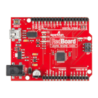
IOREF
RESET
RESET
7-15V
SCL
SDA
AREF
GND
13
12
~11
~10
~9
8
7
~6
~5
4
~3
2
1
0
TX
RX
13
3.3V
5V
GND
GND
VIN
A0
A1
A2
A3
A4
A5
POWER
ANALOG IN
DIGITAL (PWM~)
ON
ISP
TX
RX
LED
(Light-Emitting Diode)
Resistor (330 ohm)
(Orange-Orange-Brown)
Page 25