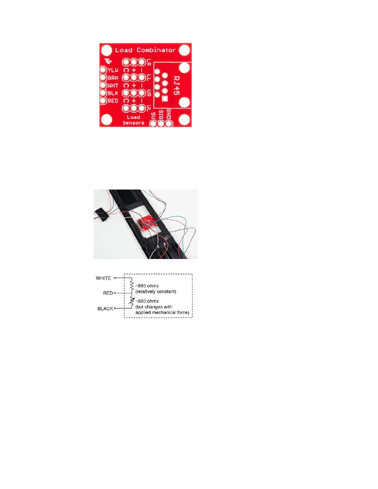
The combinator board also has room for an 8 pin RJ45 socket, which can
be used to connect your project via Ethernet cables for long distance
applications.
Another nice thing about our combinator board is that most home scales
use four single strain gauge load sensors, so this is a handy board for
hacking your own scales at home!
Hacked home scale’s four load sensors hooked up to our combinator board
Example of a single strain gauge, or load sensor. Here RED is the center
tap
For load sensors, there isn’t a set color coded standard. Comparing the
scale pictured above with the load sensor schematic, while the black wires
matched, the red and white wires were swapped. Also, only two of the four
sensors used a white wire for the ‘center tap’ of the load sensor, the other
two used green. I connected the black wires to “-”, the red to “+”, and the
white and green wires to “C”.
To determine how to hook up your single strain gauge load cells to the
combinator, measure the resistance between the three wires. You should
find a larger resistance (close to double) between a pair. In our example the
resistance between red and black was 1.6 kΩ, and the resistance between
white/green and red was 800 Ω. Therefore, the center tap to the strain
gauge is the white/green wire. The center tap or center pin of your strain
gauge connects to the “C” pin on the combinator. The larger resistance
wires (red and black in this example) connect to the “+” and “-” pins on the
combinator.
Page 7 of 10
 Loading...