board is powered externally, through this pin, the applied voltage can be up to 6V.
5V is the voltage supplied to the on-board ATmega32U4. This voltage will depend on whether you have the
jumper set to 5V (by default) or 3.3V.
When the jumper is set to 5V, it is the voltage applied to the RAW pin. We suggest using a clean 5V
power supply if you are connecting 5V devices to the I/O. If the board is powered through the 'RAW'
pin (or USB), this pin can be used as an output to 5V supply other devices.
When the jumper is set to 3.3V, the output is 3.3V. If the board is powered through the 'RAW' pin (or
USB), this pin can be used as an output to 3.3V supply other devices.
RST can be used to restart the Qwiic Pro Micro. There is a built-in reset button to reset the Pro Micro.
However, the pin is broken out if you need to access this pin externally. This pin is pulled high by a 10kΩ
resistor on the board, and is active-low, so it must be connected to ground to initiate a reset. The Qwiic Pro
Micro will remain "off" until the reset line is pulled back to high.
GND, of course, is the common, ground voltage (0V reference) for the system.
I/O Pins
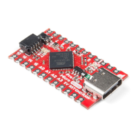
The Qwiic Pro Micro breaks out the I/O pins to plated through hole pads on the edge of the board. Each pad is
castellated as well. On the back, there are additional pins to connect to the USB data pins.
Castellated I/O PTH Pads USB Pads
The Pro Micro's I/O pins -- 18 in all -- are multi-talented. Every pin can be used as a digital input or output, for
blinking LEDs or reading button presses. These pins are referenced in the Arduino IDE via an integer value
between 0 and 21. (The A0-A3 pins can be referenced digitally using either their analog or digital pin number).
Nine pins feature analog to digital converters (ADCs) and can be used as analog inputs. These are useful for
reading potentiometers or other analog devices using the analogRead([pin]) function.
There are five pins with pulse width modulation (PWM) functionality, which allows for a form of analog output
using the analogWrite([pin], [value]) function. These pins are indicated on-board with a faint, white circle
around the square pads.
There are hardware UART (serial), I C, and SPI pins available as well. These can be used to interface with digital
devices like serial LCDs, XBees, IMUs, and other serial sensors.
2
 Loading...