18. L & R PRE-OUT – Two, RCA jacks, one pair per Zone, provide left and right line-level audio outputs for driving external
high-power/audiophile two-channel amplifiers in large or outdoor zones or a critical listening zone, or driving a multi-channel
amplifier for additional rooms, (sub-zone expansion) where needed.
19. IR OUT (Zone)
– Eight, 3.5mm mini jacks, one per zone, provides dedicated Zone IR output for exclusive control of a specific
zone component. (i.e., a dedicated satellite receiver or DVD player, that cannot be controlled from any other zones).
POLARITY: TIP=SIGNAL; SLEEVE=GND.
20. L & R SPEAKERS
– Eight, removable screw-down connectors, one terminal per zone, provide quick connection of the internal
amplifiers to Zone stereo speaker pairs.
WIRE GAUGE: 14 to 24 AWG.
21. VIDEO OUTPUT
– Eight, F-type terminals, one per zone, provide a dedicated composite video output for each zone. 75 ohm
outputs provide matched line impedance for high quality video over RG6 cable for lengths up to 500 feet.
22. VC/NVC
– Eight, two-position switches, one per zone, switch the PRE-OUT jacks to VC - internal Volume Control (variable,
zone volume controlled by keypads or IR remote) or
NVC - No Volume Control (fixed, zone volume controlled by in-wall
volume control or volume control on an external device such as an A/V Receiver). In either case, the tone control action
remains available for room “EQ” settings.
23.
IEC TYPE AC MAINS RECEPTACLE AND FUSE – One, Standard IEC 3-conductor AC line cord receptacle, connects to included AC
power cord. Also houses the rear panel replaceable AC mains fuse (T6.3AL 250V).
MKP-1.1 FEATURES
The MZC-88 System can be controlled using
SpeakerCraft EZ-Pads, IMKPs and MODE 3.1s.
Keypad configurations vary from system to system
and some parts may need to be ordered sepa-
rately.
Each keypad comes with a set of factory installed
“default buttons” plus a good variety of loose but-
tons packed with them. The default buttons can
be easily changed to meet the needs of the instal-
lation. For more information on changing keycaps,
see: MZC-88 Hardware Installation Instructions. The
MKP-1.1 shown reflects the Source configuration
of the EZ-Tools MZC-88 Default Project. A Function
Module (FKP-1.0) and Numeric Module (NKP-1.0)
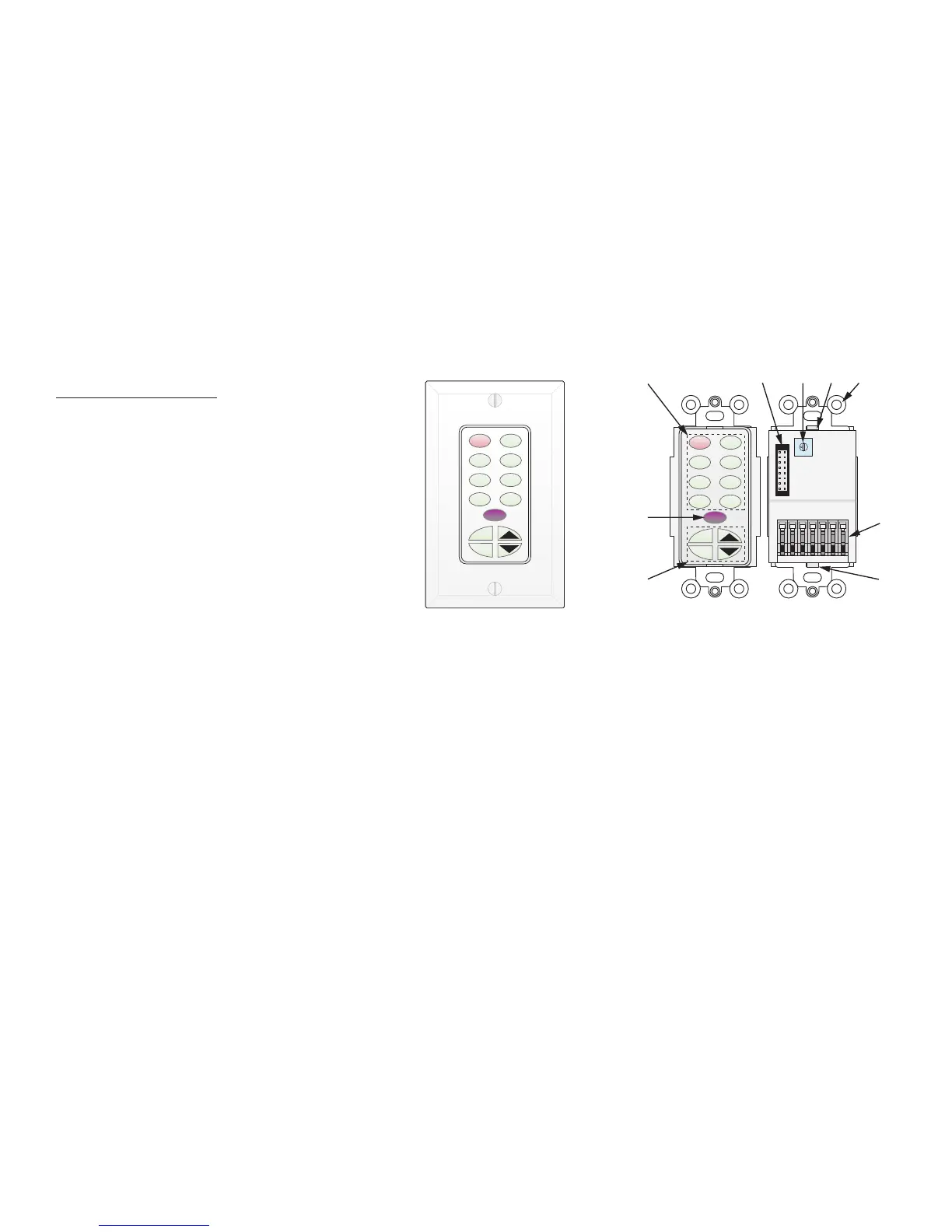
1. MKP-1.1 SOURCE/FUNCTION BUTTONS –
When used with MZC-88, six of this set of eight buttons may be programmed as source
or function buttons. The top two source buttons are dedicated to Tuner 1 and Tuner 2 when used with a MZC-88. Any mix of
source/function buttons is allowed on the remaining six, including all source or all function buttons, if desired. All buttons have
an optional green backlight, configurable in EZ-Tools. Default timeout is 60 sec. When a Source Button is pressed, it turns a
low-level red color to show that it is the active source and the system is ON.
2.
KEYPAD EXPANSION TERMINAL – This 16-pin header terminal is used to inter-connect the NKP-1.0 and FKP-1.0 modules for
expansion as needed. A ribbon cable is packed with each NKP-1.0 and FKP-1.0 for making these connections.
3.
ADDRESS SWITCH – An unique hex address must be set for each master keypad when connected on a common bus within a
single zone. Unique addresses are not required zone-to-zone. (One keypad per zone.) It provides up to 16 addresses (0 to F).
4. SNAP TABS – These tabs hold the decorator style insert panel to the metal mounting plate and are easily released for custom
changing of the buttons.
5.
MOUNTING PLATE – Standard plate allows the keypad module to be attached to standard in-wall J-Boxes using the 2 screws
provided. Allows attachment of standard decorator type cover plates (also screw-less snap-on plates).
6.
EZ-CONNECT TERMINALS – These spring-loaded terminals accept wire sizes 14 to 28 AWG for connection of the following:
+Relay/–Relay – For connection of an optional EPR-1.0 EZ-Pad Relay Speaker Muting Module. See: MZC-88 Hardware
Installation Instructions for additional information.
+12V DC –
Powers the Keypad, including the internal IR Receiver. Includes reverse voltage protection.
IR/IO (Data) –
Sends IR control signals for control of system components.
GND –
Return for Power, IR signal and Data
485 A/485 B –
Balanced, bi-directional system communications data.
7. FUNCTION BUTTONS –
These lower 4 buttons (5 buttons in the case of the MKP-1.0) can be programmed for any function
except source select.
8.
IR RECEIVER LENS – EZ-Pad version MKP-1.1 includes SpeakerCraft’s exclusive ANS IR Receiver, built-in. The IR Receiver allows
use of a handheld remote for control of system components.
A
B
C
D
E
F
0
1
2
3
4
5
6
7
8
9
TNR1 TNR2
iPOD1 CD
DVD
SAT
CBL AUX
MUTE
PWR
ADDRESS
KEYPAD EXPANSION
MKP-1.1
J-Box EZ-Pad w/IRC
-Master-
SpeakerCraft
+RELAY
-RELAY
+12V
IR I/O
GND
485 A
485 B
MUTE
TNR1 TNR2
iPOD1 CD
DVD SAT
CBL AUX
PWR
are available options for additional control capability, however, a MKP-1.1 or MKP1.0 Master Keypad is required for each zone. NKP-
1.0s and FKP-1.0s will not function on their own. See: MZC-88 Hardware Installation Instructions for additional information.
4
1
2 3 4 5
6
4
7
8
MKP-1.1 Master Keypad
Rear View
MKP-1.1
With Trim Plate (Not Included)

 Loading...