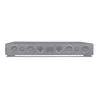
Speaker Placement
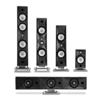
The Prole Series speakers can be used for front or rear left and right channel in a home theatre speaker system.
Installation Considerations
Before installing your speakers, you should consider the placement carefully, taking into account the location of electrical,
plumbing and other xtures, as well as studs. Contact your dealer for assistance if you are not sure of the best locations in
your particular room or home environment.
Surface Preparation
For unnished ceilings and walls, a new construction bracket (available from your dealer) may be installed prior to drywall
where a speaker will be located.
For nished ceilings and walls, mark the cut-out using the template included in the box. CAUTION: If you are not certain if an
obstruction exists behind the desired mounting area, you should start by cutting a small hole in the center of your penciled
mounting hole. Cut with your blade at a 45˚ degree angle to the surface material pointing inward towards the center of
the hole (See Figure 1). Cutting the small hole at this angle will make drywall repair much easier as the piece cut out can be
installed neatly back into place. Insert a rigid wire through the hole to locate any obstructions. Once you have determined
that there are no obstructions in your desired mounting location, cut the nished hole at a 90˚ degree angle.
Speaker Installation
Prior to actual installation of your Prole Series speakers, it will be necessary to run speaker wire (recommended 14 gauge,
two-conductor cable) to the speaker locations. CAUTION: Speaker components can get hot while playing music at
moderate to high volume levels. Maintain a minimum of 1” (25 mm) clearance between speaker components and plastic
vapor barriers and / or insulation of any type.
1. Remove the grille.
2. Attach the speaker cable observing the proper polarity with your amplier, + to + and – to -. Make sure the left channel of
the amplier is connected to the left speaker, and the right channel is connected to the right speaker.
3. Make sure the mounting feet are turned inward to clear the ceiling or wall opening, and insert the speaker. Tighten the
mounting screws on front of the bafe. CAUTION: Over tightening may warp the bafe, crack the wall surface, cause
ange to distort, and make installation difcult.
4. After all your speaker adjustments are made, install the grille back into
place.
Speaker Adjustments - NOTE: The speaker adjustments below are featured
on select models only.
The woofer rotates and pivots to almost any position. Simply apply pressure
with ngertips to the outer surface of the Pivot Ball and move the speaker to
the desired position.
Once the woofer is positioned, further renement can be made by gently
pivoting the tweeter towards the listener.
Push gently at the edge of the tweeter to point it in the desired direction.
Frequency Settings
When selected, the settings will have the following result:
-3dB: Reduces the loudness of the selected frequency (bass & treble)
0dB: The selected frequency (bass & treble) remains at neutral level
+3dB: Increases the loudness of the selected frequency (bass & treble)
When adjusting the bass frequency, the impedance will be affected as indicated below. Be sure to stay within the
impedance guidelines of the amplier you will be using to power your system.
-3dB: The impedance is 8 ohm
0dB: The impedance is 6 ohm
+3dB: The impedance is 4 ohm
Painting the Grilles
We recommend that you paint your grilles prior to installation. If you decide to paint them in the future, it is best to remove
them by simply detaching them from the speaker. When painting your grilles, great care should be taken not to clog the
holes, as this will greatly reduce sound quality of the speaker. Before painting the grilles, remove the cloth material under
grille then place it back into place after painting. SpeakerCraft recommends only light spray painting using 5 parts thinning
agent to 1 part paint. Do not paint the grilles while they are attached to the speaker. If it is necessary to paint the cloth
material under the grille, follow the same procedure used for painting the grilles.
INSTALLATION GUIDE
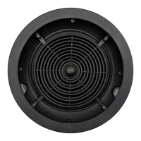
10023227 - Rev-A - Prole CRS6 ZERO Manual
PRINTING INSTRUCTIONS: 1 page front/back INK: BLACK | MATERIAL: 80lb Gloss SIZE: 8.500” x 11.000”
SIDE VIEW OF CEILING
First Cut
Second Cut
(Figure 1)