4
1. Pull four-conductor wire from each room (home runs) to the AT-1.0 near
the controlled components.
Note: Use 24 gauge unshielded solid or stranded copper wire up to
1200' (Cat. 5e ok), 22 gauge up to 2000', 20 gauge up to 3000'
and 18 gauge up to 5300'. Total lengths include all wire runs from
each room added together, not just the longest single run. If using
shielded wire, these lengths would be reduced by approx. 30%.
Also, to achieve operation with long lengths, the DIP switch must be
set to the NET ON position.
2. Connect IR receivers in each room to the four-conductor runs as shown.
3. Connect the four four-conductor home run wires to the correct terminals
on the EZ-Connect Terminals.
4. Install and plug the various emitters into the AT-1.0.
5. Set the DIP switches to EM ON (or BL ON if using blasters behind closet
doors) and NET ON.
6. Plug the local IR receiver into the IR RCVR jack.
7. Plug in the Power Supply.
8. The AT-1.0 system should now control the components.
Power Supply Note: The SpeakerCraft PS-1.0 12V DC 200 mA power supply
is adequate for this application and for most installations using only
SpeakerCraft IR Receivers. However, if you use one or more keypads in the
system, be sure to add up all the currents for each keypad, IR receiver, emit-
ter and blaster (if used) and determine the total current (see specifications
for the keypads, IR receivers, etc.). If the total current exceeds 200 mA, then
you will need to use the SpeakerCraft PS-2.0 12V DC 1.2 A power supply.
An example may serve to illustrate: Suppose you have two keypads (80 mA
each), five IR receivers (6 mA each), three emitters (15 mA each) and one
blaster (150 mA each). The total current is: 2x80 + 5x6 + 3x15 + 150 =
385 mA. Therefore, the PS-2.0 Power Supply would be necessary.
CAUTION: Never connect regulated power supplies in parallel! If you need
more current; always step up to a higher current supply, as in this example.
STATUS Brightness
Fig. 3 also shows how an external resistor can be added to reduce the
brightness of the Status LED’s on SpeakerCraft IR Receivers to any desired
level.
In this example, a PS-1.0 12V Power Supply is used as the voltage source to
indicate ON/OFF status of an AV Receiver.
Choose a resistor value that achieves the brightness you desire (about 2.2k
to 12k, 1/8 W). Connect it in series with the STATUS terminal on each IR
receiver desired, as shown.
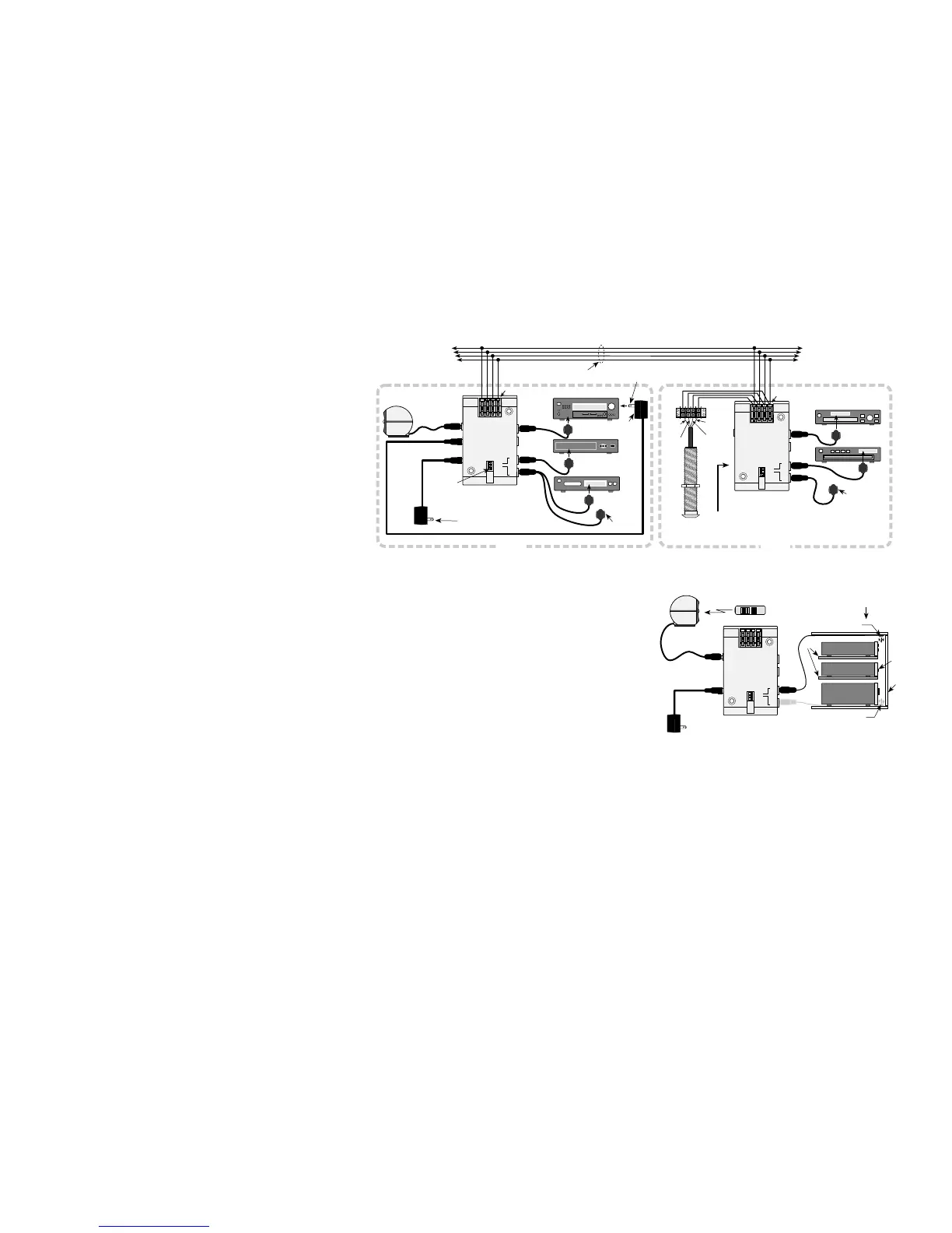
Bi-Directional IR Control
Fig. 4 is an example of a two-room system using two AT-1.0’s for Bi-
Directional control on a common IR Network. This type of connection per-
mits IR receivers (or keypads if used), located in each room, to control the
various components in both rooms, whether local or remote.
5
LIT02100
SpeakerCraft
SpeakerCraft
•
1650 Seventh Street, Riverside, CA 92507
•
800-448-0976
•
Fax 888-599-9059
www.speakercraft.com
6
1. Pull four-conductor wire between each room and connect them to the
AT-1.0’s as shown.
2. Connect the local IR receivers in each room to the IR RCVR jacks or in
parallel with the four-conductor runs at the AT-1.0 EZ-Connect Terminals
as shown.
3. Install and plug the various emitters into both AT-1.0’s as shown.
4. Set the DIP switches to EM ON (or BL ON if using blasters behind closet
doors). Set NET ON at one of the AT-1.0’s and to NET OFF on the other
one.
5. Plug a Power Supply into only ONE of the AT-1.0’s.
6. All components should now be controllable from either room.
Note: Additional AT-1.0’s may be wired into other rooms on the same
IR Network, up to about ten AT-1.0’s maximum. In every case, be sure
only ONE of the AT-1.0 Terminators on the network is set to the NET
ON position – all the others must be set to NET OFF!
Blaster Operation
Fig. 5 shows a typical basic system using the SpeakerCraft IRE-5.0 Blaster to
control a stack of components. For further details, refer to the IRE-5.0
Instructions.
1. Plug the IRE-5.0 Blaster(s) into the EMITTERS/BLASTERS port(s) on the
SpeakerCraft AT-1.0 Amplified Terminator (see Fig. 5).
2. Set the DIP switch(s) on the Terminator to the BL ON (Blaster ON) position.
CAUTION: The BL ON position sets the AT-1.0 to very high Blaster Power.
Be sure to return the DIP switch to EM ON (Emitter ON) position when driv-
ing normal emitters. Failure to do so will smoke the emitters!
3. Power the AT-1.0. Assuming other system connections have been properly
made, the components will now respond to Blaster control.
Note: Blasters draw considerable current (150 mA) when passing IR
commands. If using two blasters, power the AT-1.0 with the PS-2.0 Power
Supply, not the PS-1.0.

 Loading...