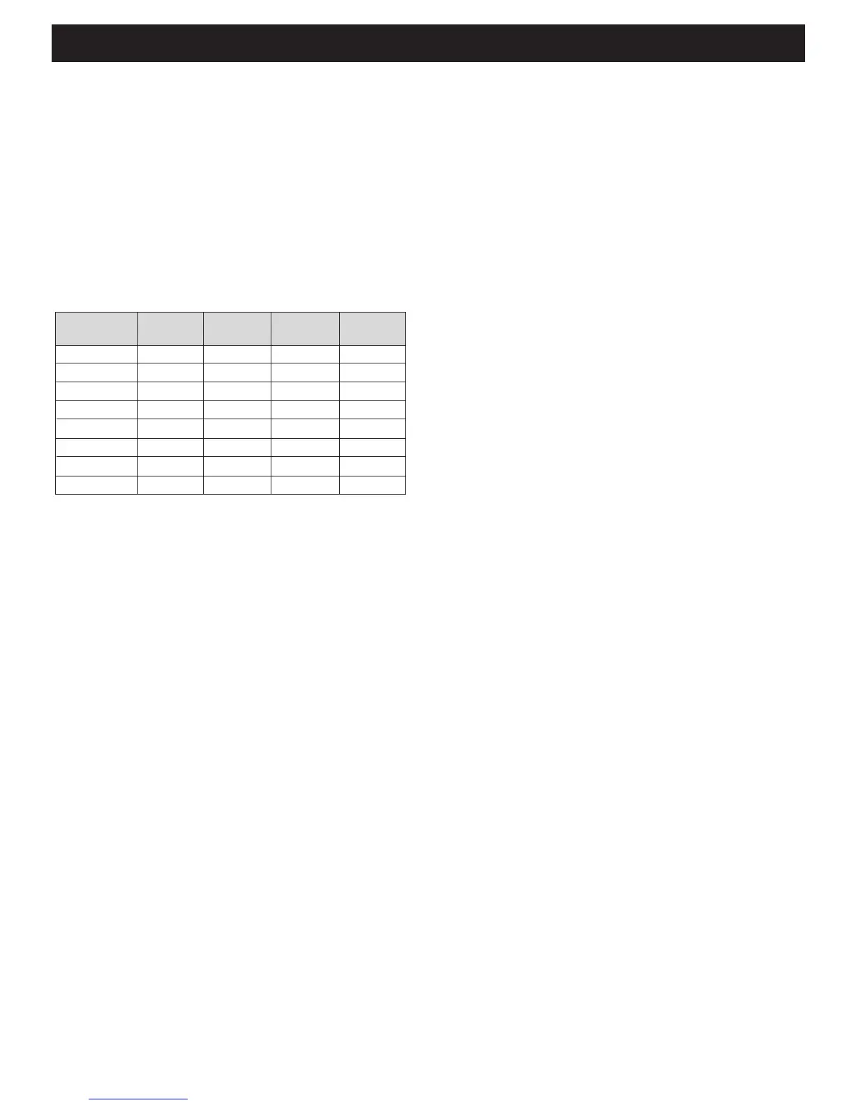
In example 1, you would set the dip switches to 0001. In Ex-
ample 2 you would set the dip switches to 0000. In example
3 you would set the dip switches to 0110.
Depending on how the zones are setup, you set the dip
switches on the TIME Controller. To setup the TIME Controller
correctly, you only have to consider the TIME Speakers in the
system, not all speakers in the system. The possible zone set-
tings and the corresponding dip switch settings are shown in
Table 2.
By setting up the zones correctly and in turn positioning the
dip switches correctly. The auto sense function on the control
hub and the zone buttons on the remote control can func-
tion as the user would expect.
NOTE: When changing the dip switch settings, make sure you
cycle power to insure that the changes are incorporated in
to the unit’s standard operations.
3. Bringing the speakers into the room - many options
When setting up the TIME Controller for the TIME Speakers.
There are many options for tuning the speakers “On” (bring-
ing speakers to their optimal playing position). The opera-
tor could do this: manually with the Power ON/OFF button
on the remote; automatically using the built in Auto Sense
Function, as described in Step 1 and 2 of this section; using
a 3V-30V AC/DC trigger voltage; by RS232 Command; by IR
commands from an IR sensor input or electrical control sys-
tem. All of these options are available and need to be setup
during the installation of the system. Consult a Authorized
SpeakerCraft Installer to determine the correct method for
the system you are installing
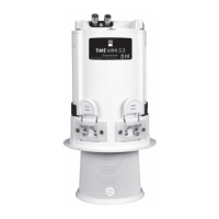
Connecting the TIME Controller
Do not plug in the AC power supply to the unit until all Loud-
speakers are connected to the TIME Controller and any pe-
ripheral control systems are plugged into the TIME Controller.
NOTE: Serious & Permanent Damage can occur to the Con-
troller or the TIME Loudspeaker, if you plug and unplug Cat
5 connectors into the TIME Controller when power is applied
to it. Always remove power to the TIME Controller when con-
necting or disconnecting Cat 5 Connectors.
Attach all TIME Speaker Power Cables (Cat 5 cable with RJ45
connectors) to the Loudspeaker and to the TIME Controller.
Pay attention to the zoning of the loudspeakers as this will ef-
fect the overall operation and control of the system.
For basic system operation using a remote, the system is now
connected. However, if a remote IR Receiver is being at-
tached to the TIME Controller, please attach it to the IR Re-
ceiver port on the Controller, as shown in the appendix. If a
SmartPath™ IR repeating system is being connected, please
attach it as shown in the Appendix.
If you are attaching a MZC™ control system using the RS232
port, connect it now. If external triggers are going to be used
to control Loudspeaker movements, connect them now.
Once all Loudspeaker Power Cables, external controls and
accessories are connected to the TIME Controller and the
Dip Switches are set, as desired, plug the supplied AC Power
connector into the unit and plug the AC Power Pack into a
AC wall socket.
The unit is now ready to program using the TIME Remote Con-
trol or the TIME Tester Application, as described in the Ap-
pendix.
PROGRAMMING THE SPEAKER LOCATIONS
AND PRESETS
The Loudspeakers can now be controlled and presets pro-
grammed for the system. See the TIME Remote Owner’s Man-
ual for details on how to use the remote to program the unit,
but the general ow of programming each loudspeaker is
as follows (see the TIME Remote in the appendix for Time Re-
mote Button locations):
1. For each loudspeaker in a zone, rst select that zone.
2. Then use the Loudspeaker Select + or – button to select the
loudspeaker you want to control.
3. When the correct Loudspeaker’s LED you want to control is
lit, press the Control button on the remote and the LED should
start ashing.
Table 2 – Dip switch (positions 5-8) Settings Table
Dip Switch Zone 1 Zone 2 Zone 3 Zone 4
(pos 5-8)
0000 Spkr 1-8 None None None
0001 Spkr 1-5 Spkr 6,7 Spkr 8 None
0010 Spkr 1-7 Spkr 8 None None
0011 Spkr 1-6 Spkr 7,8 None None
0100 Spkr 1-2 Spkr 3-4 Spkr 5-6 Spkr 7-8
0101 Spkr 1-4 Spkr 5-8 None None
0110 Spkr 1-4 Spkr 5-6 Spkr 7-8 None
0111 Spkr 1-3 Spkr 4-5 Spkr 6-7 Spkr 8
Page 3 TIME Series Controller
 Loading...