EasyManua.ls Logo

Speakman S-1495-AF - User Manual

Speakman S-1495-AF
4 pages
Print Icon
To Next Page IconTo Next Page
Loading...
INSTRUCTIONS FOR MODELS
92-S-1495-97-03
For additional assistance or service please contact:
SPEAKMAN
®
800-537-2107
customerservice@speakman.com
www.speakman.com
S-1495-AF
S-1497-LH
* Shower head may
vary between models.
HELPFUL TOOLS & SUPPLIES:
TOOLS AND SUPPLIES
Pencil
Adjustable
Wrench
Flat Tip
Screwdriver
Thread Seal
Tape
3/32" Hex Key
Wrench
(Included)
1/2” Hex Key
Wrench
(not included)
Phillips
Screwdriver
Measuring
Tape
Safety
Glasses
Level
Warranty information can be found at:
www.speakman.com
WARRANTY
Your new Shower/Bath Valve is designed for years
of trouble-free performance. Keep it looking new by
cleaning it periodically with a soft cloth. The use of
harsh chemicals and abrasives on any of the
Speakman custom finish products may damage the
finish and void the product warranty. Please be sure
to only use approved cleaners. Please contact
Speakman for any clarification of acceptable
cleaners.
This type of valve must be cleaned and maintained
on a regular basis. Periodic maintenance should be
performed at least every 12 months or after any
changes have been made to the building’s plumbing
system. Valves that are installed outdoors should be
winterized by removing all of the internal parts and
removing any standing water from the valve.
Quarterly the maximum hot temperature setting (TLS)
should be checked and adjusted accordingly.
MAINTENANCE
Cover your drain to prevent loss of parts. Be sure to
wear eye protection while cutting pipe.
SAFETY TIPS
IMPORTANT
• Be sure to read instructions thoroughly before
beginning installation.
• Be sure to have properly adjusted the Temperature
Limiting Stop (TLS) as outlined in this Installation
Manual.
• Inspect all connections after installation of valve.
• This valve has an operating range of 20-80 Psi.
• This valve is designed to be used in conjunction
with a shower head rated at 1.75 gpm (6.6 L/min)
or higher flow rate.
NOTE: This installation manual covers several
models of valves. While the appearance of your
valve may differ from those shown, the installation
method is the same.
Maximum water pressure: 125 psi static; minimum
water pressure: 20 psi flowing; minimum cold
supply temperature: 40 °F; maximum hot supply
temperature: 160 °F;
FREEZE PROTECTION
Freeze damage to the shower unit will void the Freeze damage to the shower unit will void the
warranty. It is important to winterize the complete warranty. It is important to winterize the complete
shower unit. The unit must be drained of all water shower unit. The unit must be drained of all water
in freezing conditions. This includes removing the in freezing conditions. This includes removing the
valve cartridge and the shower head from the unit. valve cartridge and the shower head from the unit.
Store the valve cartridge and shower head indoors.Store the valve cartridge and shower head indoors.
• Mounting location must be capable of supporting
the product in use.
CAUTION: When outdoor temperature
rises above 90 degrees, use caution to
prevent scalding from water stored within
the unit. It is recommended to flush the unit
by turning it on for 30 seconds before
entering the shower water. This will avoid
accidental scalding by the user and ensure
safe use of the shower unit.
1
Install the HOT and COLD supply lines for the
Valve, either through the wall, from the ceiling,
or from the floor. For ceiling and floor mounts,
hold 1” from finished wall to center of supply
lines. See rough-in diagram on last page.
1/2” NPT
CONNECTION
2
Disassemble the two Union Stops. Start by
loosening the Union Nut (1). The Union Adapter
(2) and Union Washer (3) usually stay affixed
to the Union Nut. Set the Union Body (4) aside for
later use.
X2
3
If the components in Step 2 did not stay
together, insert the Union Adapter (2) into the
Union Nut (1), followed by the Union Washer(3).
After applying Thread Seal Tape to the Union
Adapter, thread the assembly into the COLD
Inlet. Tighten with a 1/2” Allen Wrench. Repeat
for HOT Inlet.
X2
1/2"
4
Retrieve the Union Body. After the application of
Thread Seal Tape, thread the Union Body onto the
COLD supply line and tighten with the Adjustable
Wrench. The outlet of the Union Body should be
aligned horizontally. Repeat for HOT supply line.
X2
5
Slide the Strap (1) onto the Shower Arm (2).
6
Apply Thread Seal Tape to both ends of Shower
Arm Gooseneck, and Bottom Plug. Thread
Shower Arm Gooseneck into Valve Body being
sure to properly align outlet. Install Plug into
bottom port of Valve Body and wrench tighten.
7
Insert the Valve Assembly between the installed
Union Stop Bodies. Thread Union Nuts onto Valve
Body and wrench tighten, being sure Shower
Arm Gooseneck is in a true vertical position.
Turn "ON" water supply and check for leaks.
See Service Instructions for turning
"ON"/"OFF" water supply.
8
Mounting location is optional. Verify that the
mounting location and structure is capable of
supporting the product in use.
Mark location of mounting holes for Shower Arm
Strap (1) referencing the rough-in diagram
contained in this document.
Install Shower Arm Strap (1) to upper pipe using
Supplied Screws. In drywall or tile applications,
be sure to use appropriate hardware.

Other manuals for Speakman S-1495-AF

Question and Answer IconNeed help?

Do you have a question about the Speakman S-1495-AF and is the answer not in the manual?

Summary

Installation Instructions Overview

Tools and Supplies for Installation

Lists essential tools and supplies required for the installation process.

Important Installation Considerations

Key points and precautions to follow before and during installation.

Safety Tips During Installation

Essential safety advice to follow during the installation process.

Maintenance and Cleaning Recommendations

Guidelines for maintaining the shower valve for optimal performance.

Freeze Protection and Cautionary Notes

Guidance on protecting the unit from freezing and related cautionary advice.

Warranty Information

Information on where to find warranty details for the product.

Step-by-Step Installation Guide

Install Hot and Cold Supply Lines

Connect the HOT and COLD supply lines to the valve.

Connect Union Stops to Cold and Hot Inlets

Disassemble union stops and connect them to the cold and hot inlets.

Align Union Bodies to Supply Lines

Align the union bodies horizontally to the hot and cold supply lines.

Install Shower Arm Strap

Slide the strap onto the shower arm.

Install Shower Arm Gooseneck and Bottom Plug

Thread the shower arm gooseneck and install the bottom plug.

Connect Valve Assembly and Check for Leaks

Insert valve assembly, tighten union nuts, and check for leaks.

Verify Mounting Location and Install Strap

Verify mounting location and install the shower arm strap.

Handle and Dial Cap Operations

Handle and Dial Cap Removal

Steps for removing the handle and dial cap for adjustments.

Back-to-Back Installation

Procedure for adapting the valve for back-to-back mounting with reversed inlets.

Valve Cartridge Adjustment and Re-installation

Instructions for adjusting and re-installing the valve cartridge assembly.

Temperature Limit Adjustment

Guide to adjusting the temperature limit stop (TLS) for maximum outlet temperature.

Handle and Dial Cap Installation

Steps for installing the dial cap and handle onto the valve.

Final Steps and Service Instructions

Final Flush and Shower Head Installation

Turn on water supplies, flush the unit, and install the shower head.

Service Instructions: Shutting Off Water

Procedure for shutting off hot and cold water supplies to the valve.

Service Instructions: Cartridge Replacement

Steps for replacing the valve cartridge assembly and reassembling.

Service Instructions: Temperature Limit Setting

Guidance on setting the maximum outlet temperature after servicing.

Rough-In Diagrams and Part Information

S-1495-AF Rough-In Diagram

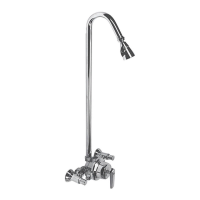
Diagram showing dimensions and connections for the S-1495-AF model.

S-1497-LH Rough-In Diagram

Diagram showing dimensions and connections for the S-1497-LH model.

Overview

The Speakman S-1495-AF and S-1497-LH are shower valve models designed for reliable and safe operation in various plumbing systems. These valves are built to provide a consistent and comfortable showering experience, with features that prioritize user safety and ease of maintenance.

Function Description:

At its core, the device functions as a thermostatic mixing valve, controlling the flow and temperature of water delivered to a showerhead. It blends hot and cold water supplies to achieve a desired temperature, while also incorporating safety mechanisms to prevent scalding. The valve is designed to operate within a specific pressure range, ensuring optimal performance and water flow. It is intended for use with showerheads that have a flow rate of 1.75 gallons per minute (6.6 liters per minute) or higher, promoting water efficiency without compromising the showering experience. The valve's internal components work in concert to regulate the water temperature, even when there are fluctuations in the hot or cold water supply pressure. This ensures a stable and comfortable temperature for the user throughout the shower.

Usage Features:

The installation process for these valves is designed to be straightforward, with clear instructions provided for both standard and back-to-back mounting configurations. Users can choose to install the hot and cold supply lines through the wall, from the ceiling, or from the floor, offering flexibility for various bathroom layouts. The valve includes union stops that facilitate easy connection and disconnection of the supply lines, simplifying future maintenance or repairs. A key feature is the Temperature Limiting Stop (TLS), which is factory-set to a maximum outlet temperature of 110°F (43°C). This safety feature can be adjusted by the user to a desired maximum temperature, providing an additional layer of protection against scalding, especially in households with children or elderly individuals. The handle and dial cap are designed for intuitive operation, allowing users to easily adjust the water temperature. The valve also supports back-to-back installation, which is useful in shared spaces where two valves might be mounted on opposite sides of a wall, and allows for reversal of hot and cold inlets if needed. This adaptability makes the valve suitable for a wide range of plumbing setups. For outdoor installations, the valve includes freeze protection guidelines, emphasizing the importance of draining the unit and storing internal components indoors during freezing conditions to prevent damage and maintain warranty validity. Conversely, for outdoor installations in hot climates, a caution is provided regarding potential scalding from water heated by ambient temperatures, recommending a brief flush before use. The design also incorporates a shower arm strap for secure mounting of the shower arm, ensuring stability and preventing movement during use.

Maintenance Features:

Maintaining the Speakman S-1495-AF and S-1497-LH valves is crucial for ensuring their longevity and continued performance. The manufacturer recommends regular cleaning of the valve with a soft cloth to preserve its finish. It is explicitly stated that harsh chemicals and abrasives should be avoided, as they can damage the finish and void the product warranty. Periodic maintenance, at least every 12 months or after any changes to the building's plumbing system, is advised. This includes checking and adjusting the maximum hot temperature setting (TLS) quarterly. The design of the valve allows for relatively easy access to internal components for maintenance. For instance, the handle and dial cap can be removed to access the TLS for adjustment. The cartridge assembly, which is central to the valve's function, can be disassembled and reassembled for cleaning or replacement. The union stops facilitate easy disconnection of the valve from the supply lines, simplifying any work that requires removing the valve from the wall. In the event of a cartridge replacement, the instructions guide the user through the process of removing the old cartridge and installing a new one, ensuring proper seating of seals and correct orientation of components. The ability to turn off water supplies at the valve itself, using a provided key, further simplifies maintenance tasks by isolating the valve from the main water lines. This thoughtful design minimizes the need for extensive plumbing work during routine servicing or repairs, making the valve user-friendly for both professional plumbers and homeowners.

Speakman S-1495-AF Specifications

General IconGeneral
TypeShowerhead
FinishPolished Chrome
MaterialBrass
Spray PatternAdjustable
ADA CompliantYes

Related product manuals