HOW TO SET SLOPES (FALLS/GRADES)
6
Working Example
The following description in this guide, explains the general principles of setting a Slope (Fall/
Grade) when using a Spectra Rotary Laser Level with the Spectra RC601UK Remote Control.
Equipment
You will need the Laser Level, a surveying tripod, measuring sta (rod) with mm scale and a laser
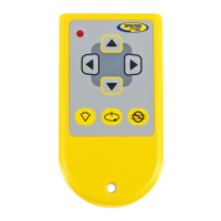
detector/receiver. You will also need the remote control or if you have arrow keys on the laser
keypad those can be used instead. If your Laser Level does not have arrow keys on the Laser
keypad, you will also need a remote control as you cannot set a gradient and slope without
this.
Site Conditions
There are many dierent work site scenarios. As an example, we are assuming that you are
outside on a site with a clear eld of view and planning to set drainage falls.
All above ground and below ground drainage pipes should be laid to an adequate gradient. The
fall in a pipe is dened as the vertical height by which the pipe drops over a known distance. e.g.
a 2.5% gradient is a fall of 1m over 40m or 1:40. (1 in 40).
Typically, surface water or foul water drainage pipes are set between 1:40 to 1:80.
If a gradient is too steep i.e. steeper than 1 in 40, the liquid may run faster than the solids in a
foul water pipe thus leaving the solids stranded, which could then block the pipe. Conversely,
if a gradient is not steep enough (usually less than 1 in 110), then the pipe may still block, if the
solids slow down and become stranded.
Procedure
Place the Laser Level horizontally on the surveying tripod, switch it ON and allow it to auto (self)
level. Note the X-axis / Y-axis markings on the top cover of the laser.
Setting a 1:40 gradient: Position the measuring sta at 10m away from the tripod, held
vertically and move the laser detector (receiver) along the sta to nd the set level position,
usually by giving a continuous audible tone. By proportion, a 1m fall at 40m is only 250mm
at 10m, so carefully noting the set level dimension on the rear of the sta, move the detector
down by 250mm and clamp tight.
Using the remote control (from the sta location) or a colleague at the laser, press the Manual
Override button and have the axis to be adjusted facing the measuring sta.
Hold the “down arrow” button on the remote control or laser’s keypad, to slope the laser beam
down the measuring sta until it gives a continuous tone again, having found set level on the
detector. This has now set a 1:40 fall.
Return the laser detector to the original set level dimension on the sta.
Dig out ground & lower sta until the laser detector picks up the laser beam again.
 Loading...