– 2 –
– 5 –
– 9 –
– 3 – – 4 –
– 6 –
– 10 –
– 7 –
– 11 –
– 8 –
– 12 –
LL200 Laser Level
User Guide
www.trimble.com
•
Introduction
Thank you for choosing the Spectra Precision
®
Laser LL200 Laser
Level from the Trimble
®
family of precision products. This simple-to-
use laser system allows you to take accurate grade reading up to 300 m
(1000 ft) in diameter.
Before using the system, be sure to read this user guide carefully.
Included in it is information about setting up, using, and maintaining
the system. Also included in this manual are CAUTIONS and Notes.
Each of these words represents a level of danger or concern. A
CAUTION indicates a hazard or unsafe practice that could result in
minor injury or property damage. A Note indicates important
information unrelated to safety.
Your comments and suggestions are welcome; please contact us at:
Trimble Construction Division
5475 Kellenburger Road
Dayton, Ohio 45424-1099 U.S.A.
Phone: (937) 245-5600
(800) 538-7800
FAX: (937) 233-9004
Internet: www.trimble.com
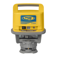
Features and Functions
Model LL200
1. Power Button – turns the laser
on/off.
2. Out-of-Level LED (red) –flashes
when the laser is out of level.
If the laser is out of level for
15 minutes, it shuts off
automatically.
3. Bull’s-Eye Level – provides
an easy reference for leveling
the laser.
4. Low-Battery LED (red) – flashes
when the battery power is low.
The laser operates for a minimum of two hours after the LED
starts flashing.
5. Level LED (green) – lights when the laser is on and level.
6. Battery Housing – holds one 1.5 V D-cell alkaline battery.
7. Leveling Base – moves around on the tripod’s leveling dome so the
laser can be leveled.
8. Leveling Dome – provides a
surface for the laser’s leveling
base to move around on so the
laser can be leveled.
9. 8-mm Cap Screws – attach the
tripod’s leveling dome to the
tripod’s legs.
10. Leg Clamps – lock/unlock so
the height of the laser can be
adjusted.
11. Legs – support the laser and
allow the height of the laser to
be adjusted.
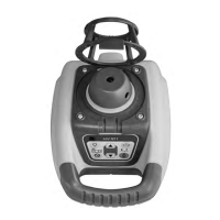
Model LL200-4
The Model LL200 and Model LL200-4
are the same except for the leveling base.
1. Leveling Screws – turn clockwise/
counterclockwise so the laser can
be leveled.
2. Threaded Brass Insert – allow the
laser to be attached to a standard
5
/8-11 construction tripod.
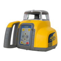
HR250 Receiver
1. Power and Audio Button –
turns the receiver on/off and
changes the audio to loud, soft,
and off.
2. Marking Notches (both sides)
– align with the on-grade
portion of the photocell and are
used to mark elevation readings.
The marking notches are 50 mm
(2 in.) from the top of the
receiver.
3. Grade-Sensitivity Button – allows you to select the receiver’s
on-grade sensitivities, which include fine: 1.5 mm (
1
/16 in.) and
medium: 3 mm (
1
/8 in.).
4. LEDs – show the position of the receiver relative to the laser beam
(above grade, on grade, or below grade).
5. Front and Back Liquid Crystal Displays (LCDs) – show the
power, audio, elevation, grade sensitivity, out-of-level, and battery
status. The LCDs also show when the laser has been bumped out of
level.
6. Photocell – detects the laser beam when it strikes the receiver. If the
photocell does not detect the laser beam for 30 minutes, the receiver
shuts off automatically.
7. Audio Port – is the opening the sound comes out of.
8. Clamp-Tab Recess – is the area
that the general-purpose clamp’s
release tab fits into.
9. Label – shows the serial number
and manufacturing date.
10. Battery Housing – holds 2 AA
alkaline batteries.
11. Battery Door – holds the batteries
securely in place.
Grade Rod 0205-2530
1. Extension-Clamp Knob – turns
clockwise/counterclockwise to
hold/release the upper rod section.
2. Release Buttons (2) – snap/
unsnap so the grade rod can be
extended/retracted.
3. Reading Edge – marks the
elevation where all grade rod
readings are taken.
4. Back-Side Scale – measures
between 0.55 m and1.36 m
(1 ft 10 in. and 4 ft 5 in.).
5. Front-Side Scale – measures
between 1.30 m and 2.11 m
(4 ft 3 in. and 6 ft 11 in.). The
upper section of both sides has an
80-cm (24-in.) scale. This scale,
which has 40 centimeters (12
inches) that are positive and 40
centimeters (12 inches) that are
negative, shows the amount of
cut/fill.
General-Purpose Clamp
The C59 general-purpose clamp allows the receiver to be attached to a
survey rod or wooden pole.
1. Release Tab – allows the receiver to be locked onto or released from
the general-purpose clamp.
2. Jaws – close/open so that the general-purpose clamp can be
attached to or released from a survey rod or wooden pole.
3. Jaws Screw – controls the closing/opening of the jaws.
4. Reading Edge – aligns with the receiver’s on-grade marking
notches.
5. Bubble Screw Holes – are where the optional 1277-6251S rod
bubble kit is mounted.
How to Use the Model LL200
CAUTION: Be sure to handle the
laser by the body rather than the top
(sunshade). The sunshade protects
the glass window that the beam
comes out of. The window can break
if handled improperly.
Receiver
1. Open the battery door using
a coin or your thumbnail.
2. Install/Remove the 2 AA
batteries noting the positive
(+) and negative (–) diagram
inside the housing.
3. Push down on the battery
door until it “clicks” into
position.
Setting Up and Leveling the Laser
1. Set up the laser in the middle of your work area (or wherever is best
for your application needs). Make sure the setup is stable.
Note: The maximum operating
diameter is 130 m (430 ft) in the
Y axis and 300 m (1000 ft) in
the X axis. The minimum operating
distance to a wall is 6 m (20 ft).
Note: For best system performance, do not set up the laser within
6 m (20 ft) of a wall. Also do not use the receiver within 6 m (20 ft)
of the laser or within 1.5 m (5 ft) of a wall. At these close ranges, the
receiver’s electronics may give incorrect beam elevation information
due to the laser beam reflecting off of the walls.
2. Press the power button to turn on the laser. All LEDs flash once to
show that they are working.
3. Level the laser using the bull’s eye as a reference.
CAUTION: When leveling the LL200, be sure not to rotate the laser
more than 360°. Doing so can cause the extension spring that holds
the laser to the leveling base to break. If rotating the laser becomes
difficult, turn the laser 180° in the opposite direction.
Note: When the laser is level, the bubble is centered in the bull’s-eye
and the green level LED lights. The LED stays lit for the first five
minutes the laser is level then flashes once every five seconds.
Attaching the Receiver to the Grade Rod
2
2
5
1
3
6
7
4
8
9
10
11
1
3
2
5
4
4
5
6
1
2
3
7
1
2
9
10
11
8
5