EasyManua.ls Logo

Spectra LR50 - User Manual

Spectra LR50
24 pages
Print Icon
To Next Page IconTo Next Page
Loading...
– 2 –
– 5 –
– 9 –
– 3 – – 4 –
– 6 –
– 10 –
– 7 –
– 11
– 8 –
– 12 –
LR50 Laser Receiver
User Guide
Introduction
Thank you for choosing the Spectra Precision
®
Laser Receiver LR50. The laser receiver
is a rugged, multi-purpose, electronic sensor that detects laser light generated by
rotating laser transmitters. The receiver works with nearly all models of rotating lasers
and detects both visible and invisible beams.
Before using the receiver, be sure to read this user guide carefully. Included in it is
information about setting up, using, and maintaining the receiver. Also included
in this manual are WARNINGS!, CAUTIONS, and Notes. Each of these words
represents a level of danger or concern. A WARNING! indicates a hazard or unsafe
practice that could result in serious injury or death. A CAUTION indicates a hazard or
unsafe practice that could result in minor injury or property damage. A Note indicates
important information unrelated to safety.
Your comments and suggestions are welcome; please contact us at:
Trimble Construction Division
5475 Kellenburger Road
Dayton, Ohio 45424-1099 U.S.A.
Phone: (937) 245-5600
(800) 538-7800
Fax: (937) 233-9004
Internet: www.trimble.com
Please record your product information below. This will assist you if there are any
questions regarding warranty or service.
PRODUCT:
SERIAL NUMBER:
DATE OF PURCHASE:
PURCHASED FROM:
PHONE:
Safety
Please follow all operating and safety instructions in this guide and that of your
machinery. Perform periodic checks of the products performance. Trimble or its
representatives assume no responsibility for results of the use of this product including
any direct, indirect, consequential damage, and loss of profits. Check your work
frequently.
WARNING: When working near construction or agricultural machinery, follow
all safety precautions as described in the machinerys user guide.
WARNING: When excavating, follow all excavation and trench safety regulations
and practices.
WARNING: Be aware of all overhead obstructions and electrical power lines.
The receiver and mast may be higher than the machinery. Remove when transporting
machinery.
CAUTION: Do not disassemble any part of the receiver other than to replace
batteries. The receiver is to be serviced by authorized Trimble service personnel only.
Maintenance and Care
Your receiver was shipped in a protective carrying case. If the receiver is transported
from job to job inside its protective case and normal instrument precautions are
followed, the receiver will provide many years of service. When storing the receiver,
be sure to store it in its carrying case.
Do not wipe dust or dirt off the receiver with a dry cloth as scratching could occur,
possibly damaging these surfaces. Use only a good quality glass cleaner with a soft
cloth on all external components. If these surfaces have hardened concrete or other
materials on them, take the system to your Authorized Service Center for cleaning.
If the receiver will not be used for more than 30 days, remove the alkaline batteries
from it. Be sure to dispose of all batteries properly. Refer to your state or local
requirements for the disposal information.
Controls and Displays
Battery Safety
Built-in overcharging protection prevents damage to the receiver if it is left on charge
after being fully charged. Charge protection also prevents damage if you accidentally
try to recharge alkaline batteries.
CAUTION: Do not attempt to charge alkaline or other disposable batteries.
Note: The batteries should only be charged when the receiver is between 0 °C to
45 °C (32 °F to 113 °F).
The rechargeable battery electronics include charge status and charge-error indicators
located on the back of the housing.
Using the Receiver
Operation
Power Button
1. Press the power button to turn on the receiver.
Notes: All the LEDs light briefly. Quickly following, each LED grade-display
row turns on and off from top to bottom and each status indicator turns on and
off. Additionally, the current deadband status and on-grade location momentarily
display. If the receiver is out of a laser beam, the center green LED flashes to
confirm power is on. If the receiver is in a laser beam, a corresponding LED grade
display lights.
2. To activate the secondary functions, press and hold the power button while the
receiver is on and then press the touch-panel buttons. These functions are indicated
by the symbols above the buttons.
3. To turn off the receiver, press and hold the power button until the LEDs light; then
release the button. Settings will be retained the next time the unit is turned on.
Blade-Tilt Button
Press the blade-tilt button to turn on/off the display. The LED status indicators display
in a rolling sequence. When the function is turned on, the LEDs sequence from the
center outward. When the function is turned off, the LEDs sequence from the outer
LEDs inward.
When blade-tilt is activated, the LEDs provide 5 channels
of tilt indication. The center LED is on when the blade or
dipper stick is within the tilt-accuracy setting. The right
side lights when the operators right side of the blade or
dipper stick is low. The left side lights when the left side
is low.
Initially the blade-tilt function is set to level. It can be set
to match the current blade slope. See “Installation” for more information.
Blade-Tilt Accuracy
Blade-tilt accuracy has three options: fine, standard and wide. To cycle through and
select one of these options, press and hold the power button; then press the blade-tilt
button. The current selection flashes rapidly. To change the current selection, continue
pressing this button combination while the status LED is flashing.
Offset on-grade is selected for typical excavation operations. This mode gives more
information and a larger display area above on-grade. This mode also enables the
plumb indication, which shows when the mast and receiver are perpendicular to the
ground (plumb), for more accurate grade readings. Each selection uses a different array
of LEDs. If you press the button once, the current on-grade location LED flashes.
Pressing the button again while the LED is flashing allows you to change the selection.
Display-Brightness Button
The display-brightness button controls the brightness for the LED grade display and
blade-tilt display. Options include Bright and Dim. Use dim for normal and lower
light conditions and bright for sunny daytime operation. Dim conserves battery life.
When the receiver is out of the laser beam and the display-brightness button is pressed,
the LEDs display a circle showing the current setting. To change the setting, press the
button again while the LEDs are activated. The LEDs then display the new setting.
When the receiver is in the laser beam, simply press the button and the setting changes.
Out-Of-Level Warning
The secondary function for the display-brightness button is the laser out-of-level
(OOL) warning. The function is used with lasers that can indicate that they are out of
level by changing their rotation speed. The factory default setting is for the warning
to be off.
To activate the out-of-level warning, turn on the receiver. Press and hold the power
button then press and release the display-brightness button. The center green LED
lights to confirm that the warning is on. Pressing the button combination again while
the “X” pattern is lit allows you to toggle between having this function turned on and
off. When the center green LED is not lit, the warning is off.
When the warning is turned on and the laser drops to 140 RPM, a flashing “X”
appears on the display to indicate that the laser is out of level.
Features and Functions
1. Aluminum-Cast Upper and Lower
Housings—protect the receiver.
2. Polycarbonate Housing—protects the
electronics.
3. Receiving Windows—include four sets of
photocells that are equally spaced to allow for
360 degree reception.
4. Super-Bright LEDs—are highly visible and
graphically display blade or bucket position.
5. Power Button—turns the receiver on and off.
6. LED Status Indicators—show on-grade
location, deadband selection, and low-battery
warning. They also function as the blade-tilt
indicator.
7. Touch-Panel Buttons—function primarily to
select blade-tilt indication, on-grade location,
deadband (accuracy), plumb indication, and
display brightness. Their secondary functions
are to select blade-tilt accuracy, plumb-accuracy
indication, laser-beam averaging, and laser out-of-level warning.
8. Mounting Knobs—are attached to stainless steel clamps. The large front-facing
knobs allow for quick and easy installation to the mast or magnetic mount.
9. Access Screws—allow easy access to battery compartment so the batteries can be
replaced.
10. Accessory Connector—accepts the cable to the optional remote display, machine
power cable, or automatic control box. The connector also accepts Ni-MH battery
charger. A dust cap covers the connector to help keep it clean.
Installing and Recharging the Batterines
Alkaline Batteries
1. Hold the receiver so the accessory connector is pointing up.
2. Remove the dust cap from the accessory connector.
3. Loosen the two thumb screws and remove the battery-access cover.
4. Install four “C” cell alkaline batteries as shown on the label diagram inside the
battery compartment noting the (+) and (–) terminals.
5. Replace the battery-access cover. Firmly tighten the two thumbscrews.
6. Replace the accessory-connector dust cap.
Nickel Metal Hydride Batteries (Ni-MH)
Rechargeable batteries require an initial and subsequent charging time of
approximately 3 hours. Two or three charging cycles may be required to obtain
maximum battery life. To charge:
1. Remove the dust cap from the accessory connector.
2. Insert the cannon adapter into the receiver
accessory connector aligning the slot and
connector key. Insert the charger female barrel
into the cannon adapter.
3. Make sure the proper AC prongs are on the charger.
Note: To change the prong adapter, press the tab release in the direction indicated
by the arrow and remove the existing prong. Insert the proper adapter and release
the tab.
4. Plug the charger into an appropriate outlet. The receiver will not operate when it
is charging.
Note: The charge-status indicator located on the back of the housing remains
solid when the batteries are charging. The left LED flashes when the batteries are
fully charged.
5. When the batteries are charged, unplug the charger from the outlet, and remove
the cannon adapter from the accessory connector. Replace the dust cap.
Center/Offset On-Grade Button
Center on-grade is selected for typical grading or cut/fill operations. This mode
indicates an equal amount of grade information above and below on-grade.
Plumb Indication
The plumb indication shows when the mast and receiver are perpendicular to the
ground or beyond the selected deadband range. The grade-display LEDs flash quickly
when the boom is extended, flash slowly when the boom is retracted beyond this
range, and remain lit when the boom is within the plumb range setting.
Plumb-Accuracy Indication
Plumb accuracy has three options: fine, standard, and wide. To cycle through and
select one of these options, press and hold the power button; then press the on-grade
location button. The current selection flashes rapidly. To change the current selection,
continue pressing this button combination while the status LED is flashing.
Charge Status Indicator: The LED remains solid when the batteries are charging.
The LED flashes when the batteries are fully charged. When the batteries are charged,
unplug the charger from the outlet, and remove the cannon adapter from the accessory
connector.
Charge Error Indicator: The LED is solid when the internal battery connection has
an error, the batteries are installed incorrectly, the battery type is incorrect, or a battery
cell is dead. A flashing LED indicates that the temperature is too hot/cold to charge.
Charging automatically starts when the temperature is within the above noted range.
Battery Replacement
1. Remove the dust cap, loosen the two thumb screws, and remove the battery-access
cover
2. Remove the old batteries. Install new batteries as previously described. See
Alkaline Batteries” for more information.
3. Replace the access cover, firmly tighten the two screws, and replace the dust cap.
Note: Refer to your local requirements for proper battery disposal.
Fine
± 0.5º
Standard
± 1.5º
Wide
± 2.5º
Center
On-grade
Selected,
Plumb Off
Center
On-grade
LEDs used
Offset
On-grade
Selected,
Plumb On
Offset
On-grade
LEDs used
Solid
LEDs
Slow
Flashing
Fast
Flashing
Fine
± 0.5º
Standard
± 1.5º
Wide
± 2.5º
Fine
Standard
Wide
Center On-Grade
(Grading)
5 mm
(0.20 in.)
10 mm
(0.40 in.)
20 mm
(0.80 in.)
Offset On-Grade
(Excavating)
12 mm
(0.50 in.)
25 mm
(1.0 in.)
50 mm
(2.0 in.)
Deadband (Accuracy) Button
Each on-grade location has three deadband or accuracy selections: fine, standard,
and wide. The center or grading deadbands are smaller than the offset or excavating
deadbands.
To show the current selection, press the button once; the status LED flashes. To
change the current selection, press the button again.
Beam Averaging
The secondary function for the deadband button is beam averaging. The beam-
averaging function senses the laser strikes and applies the highest level of averaging
appropriate for the laser rotation speed. Averaging stabilizes the LED display in
unstable laser setups, such as windy conditions or long-range applications. The factory
default setting is for beam averaging to be on. The beam-averaging function can also
be turned off. When the function is off, the receiver processes and displays each laser
strike.
To change between having this function turned on or off, press and hold the power
button then press and release the deadband button. The outer green on-grade LEDs
flash to indicate that averaging is selected. When the center LED is on, averaging is
on. When the center LED is off, averaging is off. Pressing this button combination
while the LEDs are activated changes the current selection between on and off.
Averaging ON Averaging OFF
Laser Out of Level OFF Laser Out of Level ON
Standard
DeadbandFine
Deadband
5-Light Blade-Tilt Indication
On-Grade
Location Indicators
Center
On-Grade,
Grading
Wide
Deadband
Deadband
(Accuracy)
Indicators
Offset
On-Grade,
Excavating,
Plumb On
Low Battery
Indicator
Combination
Touchpanel Buttons
Primary Function
Secondary Function
Blade-Tilt
Accuracy
Plumb Accuracy
Indication
Display
Brightness
Button
Laser-Beam
Averaging
Center/Offset
On-Grade Button
Plumb On / Off
Blade-Tilt
Button
Deadband
(Accuracy)
Button
Laser
Out-of-Level
9
8
6
5
4
3
2
1
1
8
10
9
3
7
Cannon Adapter
Charger
Charge Status Indicator
Solid – Charging
Flashing – Charging Complete
Charge Error Indicator
Solid – Battery Problems
Flashing – Temperature Out-of-Limits
(Located on lower rear of polycarbonate housing)
Question and Answer IconNeed help?

Do you have a question about the Spectra LR50 and is the answer not in the manual?

Summary

Safety

General Safety Precautions

Provides essential safety instructions, warnings, and cautions for operating the receiver.

Features and Functions

Controls and Displays

Installing and Recharging the Batteries

Battery Installation and Charging

Instructions for installing alkaline and recharging Ni-MH batteries.

Battery Safety

Battery Safety and Indicators

Information on safe battery charging, handling, and error indicators.

Battery Replacement

Replacing Receiver Batteries

Step-by-step guide for replacing alkaline and Ni-MH batteries in the receiver.

Using the Receiver

Receiver Operation Basics

Details turning the receiver on/off, using the power button, and accessing secondary functions.

Installation

General Installation Guidelines

Covers general safety, setup, and mounting instructions for the receiver on a mast.

Specifications

Warranty

Overview

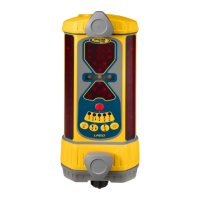
The Spectra Precision LR50 Laser Receiver is a rugged, multi-purpose electronic sensor designed to detect laser light generated by rotating laser transmitters. It is compatible with nearly all models of rotating lasers and can detect both visible and invisible beams. The receiver is intended for use in construction and agricultural applications, providing precise grade readings and machine control.

Function Description

The LR50 Laser Receiver's primary function is to detect laser beams and provide visual indications of blade or bucket position relative to the laser plane. It features four sets of photocells, equally spaced to provide 360-degree reception of the laser beam. Super-bright LEDs graphically display the blade or bucket position, making it highly visible in various lighting conditions.

The receiver includes LED status indicators that show on-grade location, selected deadband (accuracy), and a low-battery warning. These indicators also function as a blade-tilt indicator, providing visual feedback on the blade's side-to-side position.

Touch-panel buttons allow users to select various operating modes and settings. These include blade-tilt indication, on-grade location, deadband (accuracy), plumb indication, and display brightness. Secondary functions accessible via button combinations include blade-tilt accuracy, plumb-accuracy indication, laser-beam averaging, and a laser out-of-level warning.

The receiver also has an out-of-beam (OOB) function, which indicates when the receiver has moved beyond the vertical laser-reception range. This function helps guide the operator on which direction to move the blade or cutting edge to reacquire the laser beam.

Usage Features

The LR50 is designed for ease of use and versatility in the field.

Power and Battery Management:

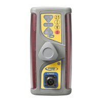
The receiver is powered by four "C" cell alkaline batteries or four "C" cell Nickel Metal Hydride (Ni-MH) rechargeable batteries. An accessory connector allows for connection to an optional remote display, machine power cable, automatic control box, or Ni-MH battery charger. A dust cap protects this connector.

To turn the receiver on, press the power button. All LEDs will briefly light up, followed by a sequence of LED grade-display rows and status indicators turning on and off. The current deadband status and on-grade location are momentarily displayed. If no laser beam is detected, the center green LED flashes to confirm power is on. If a laser beam is present, a corresponding LED grade display lights up. To turn off the receiver, press and hold the power button until the LEDs light, then release. Settings are retained for the next power-on cycle.

Secondary functions are activated by pressing and holding the power button while the receiver is on, then pressing the desired touch-panel button. These functions are indicated by symbols above the buttons.

Blade-Tilt Function:

The blade-tilt button toggles the blade-tilt display on and off. When activated, the LEDs provide 5 channels of tilt indication. The center LED illuminates when the blade or dipper stick is within the set tilt-accuracy. Right-side LEDs light when the operator's right side of the blade or dipper stick is low, and left-side LEDs light when the left side is low. The blade-tilt function is initially set to level but can be adjusted to match the current blade slope for slope matching operations.

Blade-tilt accuracy has three options: fine (±0.5°), standard (±1.5°), and wide (±2.5°). These can be cycled through by pressing and holding the power button, then pressing the blade-tilt button. The current selection flashes rapidly, and continued pressing changes the selection.

On-Grade Location:

The Center/Offset On-Grade button allows selection between "center on-grade" for typical grading/cut/fill operations and "offset on-grade" for excavation. Center on-grade provides an equal amount of grade information above and below on-grade. Offset on-grade provides more information and a larger display area above on-grade, and also enables the plumb indication for more accurate grade readings. Each selection uses a different array of LEDs. Pressing the button once flashes the current on-grade location LED; pressing it again while flashing changes the selection.

Plumb Indication:

The plumb indication shows when the mast and receiver are perpendicular to the ground (plumb) or beyond the selected deadband range. Grade-display LEDs flash quickly when the boom is extended, flash slowly when retracted beyond range, and remain lit when within the plumb range setting.

Plumb accuracy also has fine (±0.5°), standard (±1.5°), and wide (±2.5°) options, selected by pressing and holding the power button, then pressing the on-grade location button.

Deadband (Accuracy) Selection:

Each on-grade location has three deadband or accuracy selections: fine, standard, and wide. Center or grading deadbands are smaller than offset or excavating deadbands. Pressing the deadband button once shows the current selection (status LED flashes); pressing it again changes the selection.

Beam Averaging:

The secondary function of the deadband button is beam averaging. This feature senses laser strikes and applies the highest level of averaging appropriate for the laser rotation speed, stabilizing the LED display in unstable setups (e.g., windy conditions, long-range applications). The factory default is "on." When off, the receiver processes and displays each laser strike individually. To toggle, press and hold the power button, then press and release the deadband button. Outer green on-grade LEDs flash to indicate selection; center LED on means averaging is on, off means averaging is off.

Display Brightness:

The Display-Brightness button controls the brightness of the LED grade and blade-tilt displays, with "Bright" and "Dim" options. Dim is for normal/lower light conditions and conserves battery life; Bright is for sunny daytime operation. When out of the laser beam, pressing the button displays a circle showing the current setting; pressing again changes it. When in the laser beam, simply pressing the button changes the setting.

Out-Of-Level Warning:

The secondary function of the display-brightness button is the laser out-of-level (OOL) warning. This function works with lasers that indicate out-of-level status by changing their rotation speed. The factory default is "off." To activate, turn on the receiver, press and hold the power button, then press and release the display-brightness button. The center green LED lights to confirm it's on. Pressing the button combination again while the "X" pattern is lit toggles the function on/off. When the center green LED is not lit, the warning is off. When activated and the laser drops to 140 RPM, a flashing "X" appears, indicating the laser is out of level.

Low-Battery Warning:

The receiver has low-battery warning LEDs. During normal operation, these LEDs are off. When batteries are low, they begin flashing, providing approximately 90 minutes of remaining battery life. When batteries are too low for normal operation, the LEDs remain on, the four corner grade-display LEDs flash, and the receiver stops receiving laser signals. Batteries should be replaced or recharged. This warning does not operate when connected to machine power.

Installation:

The receiver mounts to round tubing (42-50 mm outside diameter) or square tubing (38 mm). Mounting knobs allow for quick and easy installation to a mast or magnetic mount. The blade-tilt and plumb indications are measured internally, requiring proper alignment of masts and receivers to the machinery for accurate readings.

Grading and Excavating Setups:

Detailed instructions are provided for both grading and excavating applications, including in-trench and out-of-trench setups. These involve positioning the machine, setting up the laser, mounting the receiver, and adjusting its height to achieve on-grade readings.

Slope Matching:

The blade-tilt indicator can be nulled to match an existing slope or set to a predetermined slope other than level. This is achieved by positioning the blade at the desired slope, ensuring receiver alignment, then pressing and holding the power, blade-tilt, and display-brightness buttons until a "0" followed by a "Y" symbol displays. To reset to level, the blade is positioned level, and the procedure is repeated. This also corrects display issues if the mast is misaligned.

Maintenance Features

The LR50 is designed for durability and ease of maintenance.

Housing and Protection:

The receiver features aluminum-cast upper and lower housings for protection, and a polycarbonate housing to protect the internal electronics. It is shipped in a protective carrying case, and storing it in this case when not in use helps ensure many years of service.

Cleaning:

To prevent scratching, dust or dirt should not be wiped off with a dry cloth. Instead, a good quality glass cleaner and a soft cloth should be used on all external components. If hardened concrete or other materials are present, the system should be taken to an Authorized Service Center for cleaning.

Battery Replacement and Charging:

For alkaline batteries, access screws allow easy entry to the battery compartment for replacement. The receiver will not operate while Ni-MH batteries are charging. The charge-status indicator on the back of the housing remains solid during charging and flashes when fully charged. A charge-error indicator provides feedback on battery connection, type, or temperature issues. Built-in overcharging protection prevents damage to the receiver. If the receiver will not be used for more than 30 days, alkaline batteries should be removed. Proper disposal of all batteries according to local requirements is emphasized.

Service:

The receiver is designed to be serviced only by authorized Trimble service personnel. Users should not disassemble any part of the receiver other than to replace batteries.

Spectra LR50 Specifications

General IconGeneral
Channel Capacity128 channels
Dimensions120mm x 55mm x 35mm
Weight220g (with battery)
Data LoggingYes
Operating Temperature-20°C to +60°C
Audio Output1W
Receiver TypeSuperheterodyne
GNSS SupportedGPS, GLONASS, BeiDou
CommunicationBluetooth, USB
Channel Bandwidth12.5kHz/25kHz
Output Impedance50 Ω
Frequency Range400-470MHz

Related product manuals